- Tue Dec 16, 2014 3:00 pm
#177795
Hello,
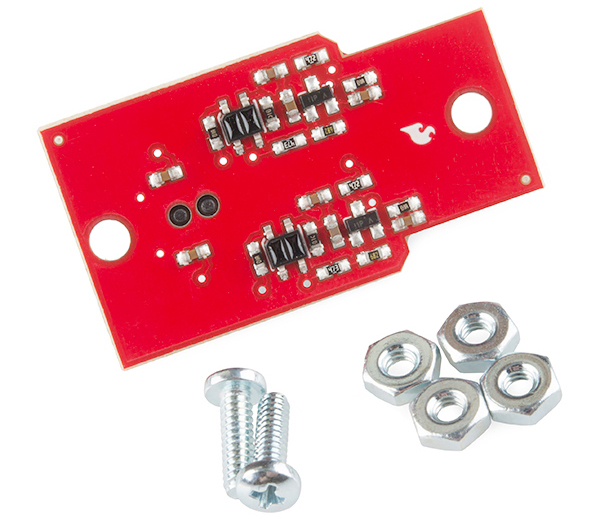
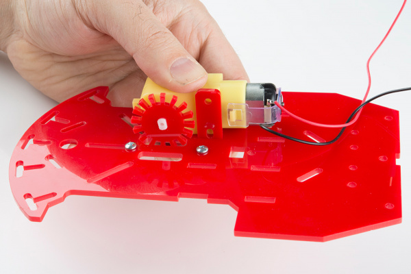
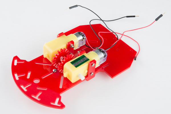
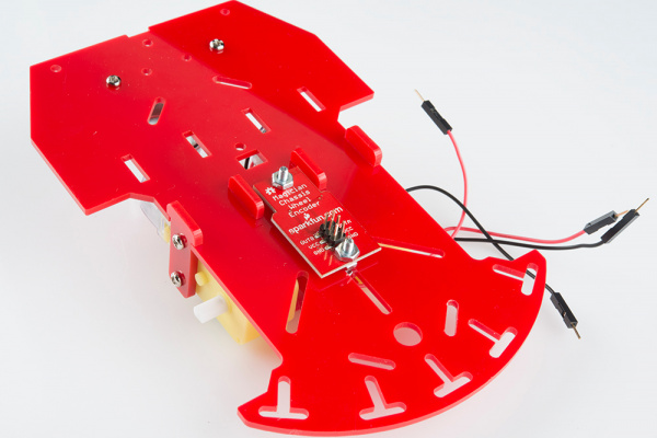
I'm using the same wheel encoders/sensor as described here: https://learn.sparkfun.com/tutorials/re ... mbly-guide (I'm using blue chassis, but the encoder disk is the same as in pictures in that guide - 16 teeth). I'd like to use the data from encoders to calculate proper PWM values to make it go (at least roughly) straight, however, I'm getting irregular readings.
If I attach the interrupt to RISING or FALLING I'm not getting 16 ticks per each full wheel revolution...more often it's less than that. Normally I'd expect to have some false ticks which I'd then filter out, but instead of this it seems not to register some proper ticks.
Anyone here has experience with this gear? Is it just not accurate enough or it needs some special treatment (checking teeth/sensor distance etc)? I'd also love to find some info on how does it work exactly: as far as I know, the sensor consist of two IR sensor - when exactly should it produce HIGH/LOW? What can affect it?