- Sat Jun 09, 2007 12:55 pm
#31115
I need some help.I very new to the world of microcontrollers and programming codes.But i've got friends that are going to help me.
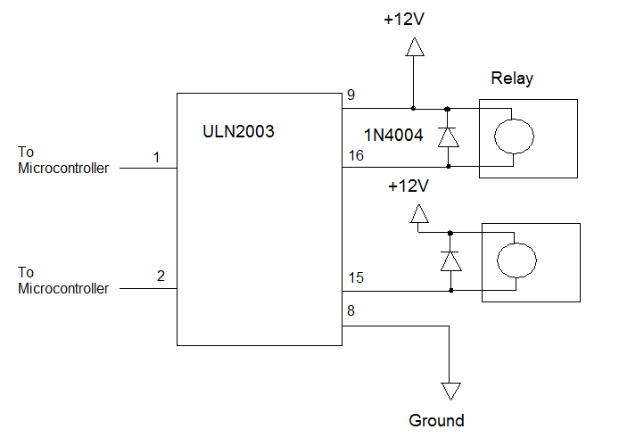
The project I'm starting is for my truck.i need to know how to wire 2 different darlington array chips to a set of automotive relays.the 1st one is a ULN2003A chip array.
the 2nd is a Mitsubishi M54661P quad array.here is the link to the chip. http://exdwh.com/M54661P.pdf
which one of these chips would work in the project im building? i know that the m54661p has an output rating of 1.5 amps per output to control the relays,and that is enough i think to control the coil of the relays.
i need to control the switching of the regular automotive type relays.there are going to be 12 relays on a pcb to control all the high power accessories that will be on the truck.
Can anyone help me with the wiring? Thanks

