SparkFun Forums 

Where electronics enthusiasts find answers.

Questions relating to designing PCBs
By snarfer
#42527
I wonder if anyone has actually created a footprint for Luxeon Rebel as described in the datasheet, with all those vias and shapes and stuff. I tried creating one in Eagle, but when I tried to use it I got a bunch of annoying errors about invalid polygons.

Please note that I am talking about the footprint for FR-4 PCBs. It is very different from the footprint for metal core.
By propellanttech
#42528
snarfer wrote:I wonder if anyone has actually created a footprint for Luxeon Rebel as described in the datasheet, with all those vias and shapes and stuff. I tried creating one in Eagle, but when I tried to use it I got a bunch of annoying errors about invalid polygons.

Please note that I am talking about the footprint for FR-4 PCBs. It is very different from the footprint for metal core.
I looked at that datasheet....and was going to try, but I do not know where you could get that board made cheaply.

The small via's at the LED are smaller (I believe) that what Batch PCB or Gold Phoenix will do.

Who ever does it is going to have fun......lots of vias.

James L
User avatar
By leon_heller
#42529
My usual supplier, PCB-Pool, could do that. They can do vias down to 0.3 mm.

Leon
By snarfer
#42530
That's a really good point about the via size. The outer vias are already at the limit for a lot of manufacturers, but the two inner vias have 10 mil inner diameter.

34 vias per LED. 96 on a board. That would make 3264 vias. Yeah that will be fun to make.

I'm sure I can get it done, but it might end up just as expensive as getting a metal core PCB!
By snarfer
#42532
eprotos.com says minimum finished hole size of 6 mil for laser cut and 10 mil for mechanical. That's 0.152 mm and 0.254 mm respectively, if you don't have a calculator handy.

Anyway, back to the subject at hand! Anyone successfully make a footprint?
By kaiki
#45630
I made a board using 20mil drills. I have 32 holes in and around one Rebel. and 3 led's on a board.
The board is fixed to a heatsink using thermal adhesive grease.
It doesn't also help that its a 0.062 inch thick board.

However with each led running at 1W and the input supply sourcing 5W's, I see the attached heatsink going upto around 52 C. Which at ~10C/W for the rebel, sounds almost right for the amount of dissipated heat.
User avatar
By ohararp
#45631
Kaiki,

Think you could post some pictures of your design?

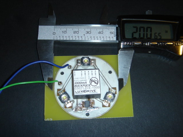
I am working on a design that currently uses K2 Luxeons.
Image

First version uses buckpucks, versions b and c use some other drivers. Anyways, I want version d to use Luxeon Rebels. My initial tests and research are showing that 15 mil vias, .032" FR4 and dual sided pcbs with thermal ground planes are gonna work for this design.

Shane at Gold Phoenix quoted USD250 for 100inch sq - minimum order for a single layer metal core pcb. Not bad if you ask me.
By kaiki
#45785
sorry, don't have pictures.

but my design is just a copy of the Rebel datasheet's recommendations for through hole's. except i used a larger drill size than what they recommended.
By Dario
#49484
I believe I saw an Eagle Library part for a Rebel mounting board
with lots of vias on the LumiLeds web site.
User avatar
By ohararp
#49500
So more testing in this area has quickly brought me to the conclusion that if you want to run these high lumen leds you MUST run them on a Metal Core PCB (MCPCB). The heat produced under such a small area is just to high. Additionally, these MCPCB's must be directly connected to an appropriate heatsink as well.
By snarfer
#52169
MCPCBs are quite expensive and difficult to source. Some discussions on Candlepowerforums have pointed out the possibility of using thicker copper weights, such as 4 oz. copper, along with thinnest available FR-4, as a viable alternative.

As my Luxeon Rebel order has been on backorder for months now, I decided to move on to other manufacturer's offerings...
User avatar
By phalanx
#52384
Advanced Circuits will make holes down to 10mil (0.254mm) on prototype boards and I believe on their bare bones boards as well.

On way to to get a good thermal bond to the bottom layer is to plug your vias with solder which increases the surface area the heat can flow through. You don't have to worry about electrical isolation with the rebels which makes this a convenient solution. I then use thermal grease between the PCB and a metal heatsink and then use bolts to link the two together.

-Bill
By Oznog
#55630
I have been doing quite a bit of research into MCPCB vs FR4 PCB with thermal vias, got heavily involved with the math, and including some actual measurements. More is possible than what was laid out in Luxeon's app note. I have come to disagree with several aspects of their thermal design they outlined there. They held back.

There are a lot of details and some catches to the design process. However, get this- thermal via construction can outperform MCPCB for any electrically-neutral thermal path emitter such as the Rebel. Even with poor design it competes. With excellent layout it can beat out MCPCB even when using Gold Phoenix standard 0.064" FR4 and 1oz copper.

IF special features are employed (thinner FR4, thicker copper), then thermal via construction blows MCPCB out of the water.

However, this may be unnecessarily expensive. If you're running 1W LEDs and only have 4C/W in the thermal board and the Rebel itself is 10C/W junction-to-pad then there's little practical reason to spend a lot of $ for unusually thick copper and special-order thin board to get the thermal resistance of the thermal via board down to 2C/W. Most mfgs charge quite a premium for anything unusual.

MCPCB is a necessarily evil for non-isolated thermal pad devices, but a somewhat poor choice for these isolated thermal pad device. There's no need for that electrical insulating layer and it comes with a significant thermal conductivity penalty. The MCPCB can still be "adequate" though for a single emitter per Star setup, since those MCPCB Stars cost like $0.50 well that's probably a good choice overall. If you want more than one device per Star then the MCPCB may show increasingly poor performance but a thermal via can perform with fairly high density without much increase in per-device thermal resistance at all. If you need a custom design, MCPCB is the wrong choice. It's both expensive and offers only limited performance.

At least that's what I got from looking at the specs and thermal measurements of MCPCB commonly used in Stars. I know there's a solid copper-core MCPCB and ones with higher tech insulators. I don't expect this tech to be readily accessible so I didn't look much into it.

Filling the vias with solder does little to improve the thermal resistance actually. The volumetric thermal resistance of solder is relatively high and the column diameter is tiny. That's easily calculated, on the larger 0.5mm vias it reduced resistance by ~25% (much less on smaller vias) and I see no reason to doubt the applicability of the numbers I got. But the real problem is that allowing solder to flow through the vias to the back results in solder flowing onto the back, reducing the flatness which will increase the board-to-sink resistance. Can't put soldermask back there! As usual I came up with some somewhat elaborate tricks to make this work but seeing it's only 25% improvement at best then it's "nice" but may not even justify the effort.

Unfortunately, note that home etching cannot produce thermal-via construction because it won't produce plated through-hole vias.
By Lucien
#55838
Oznog, that's pretty interesting. Do you have any more details on how best to go about designing a FR4 board like that? e.g. how many vias and would you place any under the isolated thermal pad?

I was looking at the Cree LEDs, but the theory should be the same.