SparkFun Forums 

Where electronics enthusiasts find answers.

General project discussion / help
Did you make a robotic coffee pot which implements HTCPCP and decafs unauthorized users? Show it off here!
By steff1
#185643
Hi,
New user here, and I'm pretty unfamiliar with circuit boards and low-voltage stuff. I have been learning some basic electronic by working on the 220V :shhh: - So please bear with me if I'm a slow learner!

Project: Change the Switches on a Remote

So I have this Remote Switch Set that lets me switch electrical outputs or lights On and Off.
ImageImage

And I want to make a new and sexy, custom remote-control for it using some nice vintage toggle switches I have been saving forever, hoping to one day sit down and learn to solder.
Image

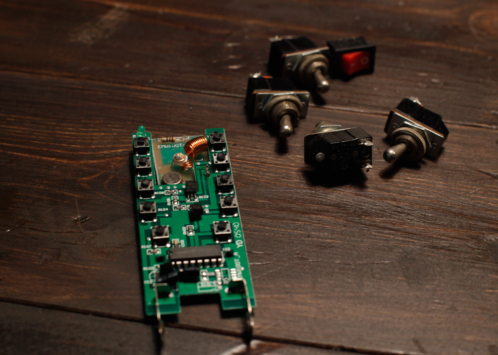
When I cracked open the original plastic remote, I realized that I have a problem!
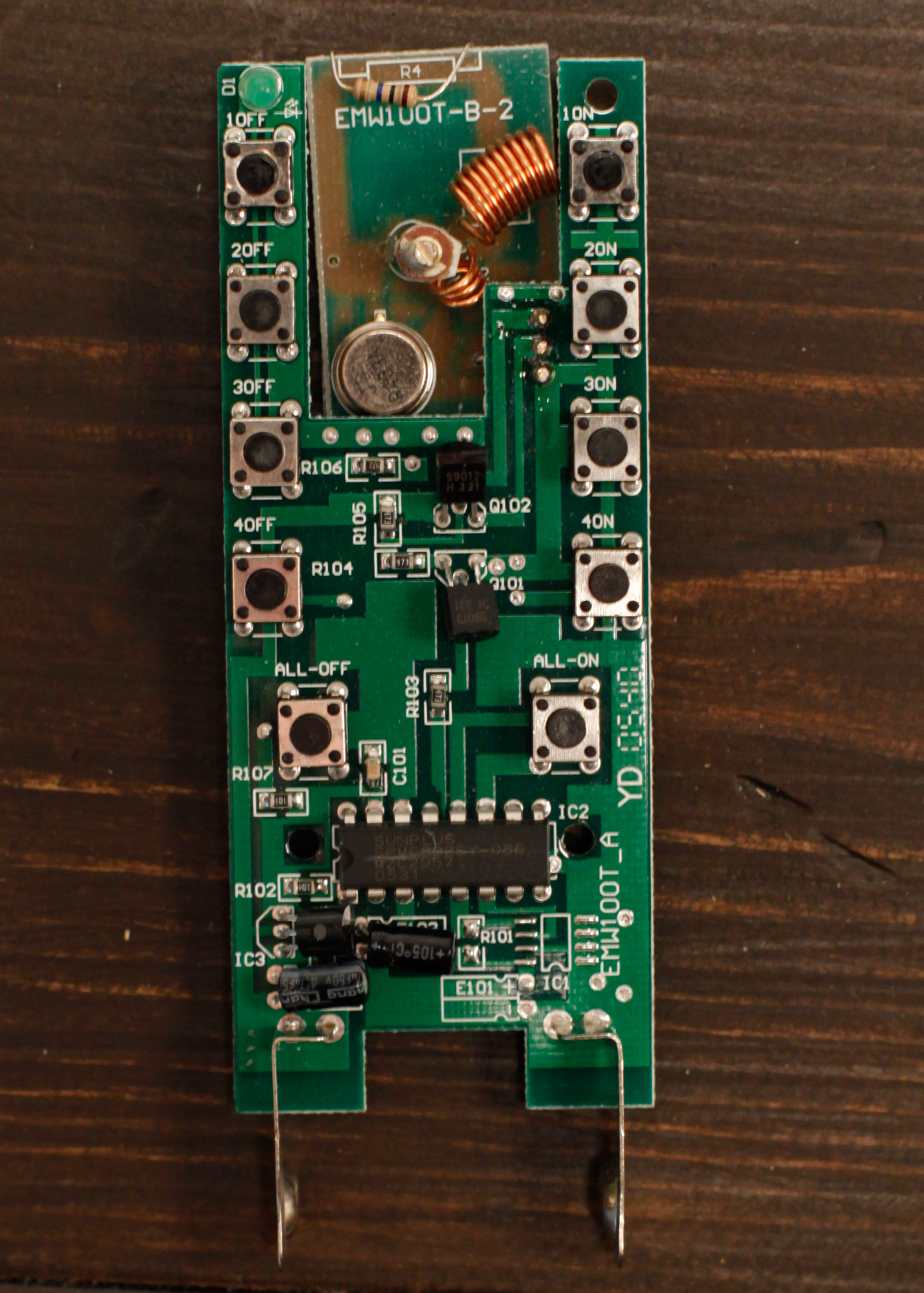
The buttons are (what I think you call) Momentary Pushbutton Switches - One for ON and one for OFF on each channel. Which for me is a completely different thing than allowing current flow if a switch is set to ON. And another bad feeling I get is that I'll be "constantly pushing ON" and causing problems / drain the transmitter battery.

>> Is it at all possible to do what I intend?
>>> Can you help me get started?


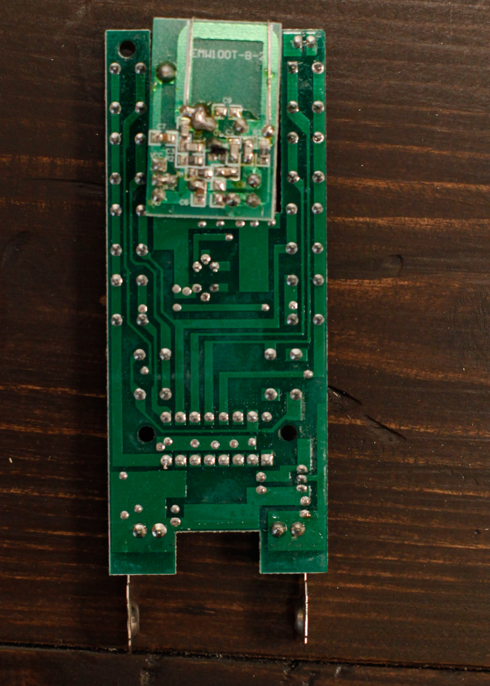
Here are some closeups of the circuitboard:
Image Image
By steff1
#185668
I'm posting a quote from a user on Stack Overflow who has a similar question, but who defines it better than me:
...Here is my desired outcome: When I flip the toggle switch from Position 1 to Position 2, Momentary Switch 1 gets connected for a moment. When I flip the toggle switch from Position 2 to Position 1, Momentary Switch 2 gets connected for a moment.

I do not need to have the physical momentary switches. I could desolder them and connect wires to each terminal.

I am hoping this could be done with very few components (maybe digital logic gates) and no microprocessors would be involved.
:idea: Basically a system that allows us to use one toggle switch instead of two momentary switches. I'm sure this is something more people could find useful / fun as well. But after two days of googling I'm coming up blank as far as solutions go.
By lyndon
#185685
This is not a bad project for a beginner. You need two optocouplers to connect to the two momentary switches, two one-shots that are triggered by the toggle and logic so one of the one-shots is triggered on a LOW transition and the other is triggered on a HIGH transition.

Now go google what all those terms mean :-) Seriously, I think it's a much better beginner project than the people who are "new to electronics and want to build a cell phone."
By steff1
#185790
Thanks Lyndon.

I was thinking that desoldering some plastic switches and replacing them would be a decent place to start learning, even before you started pumping out acdc-slang I knew I was in a bit over my head - but glory comes to those that dare, right?
I have about 17 tabs open right now and I have been watching a ton of youtube - I'm still struggling to visualize the concept and schematics for this. But like I said, please bear with me. I might not be smart, but I can be stubborn as hell. 8)

While researching these terms and learning a little bit about capacitators, resistors, breadboards and whatnot I've also come across a few other pages and ideas that are doing somewhat the same thing I will be trying to achieve here (all though there are a lot more tutorials on the opposite system, known as flip-flops / latch - where a momentary switch is used as a toggle switch).Anyway I'll list them for reference and in case someone else who are on a similar mission finds this thread.

http://www.simprojects.nl/toggle_to_momentary.htm (using a relay)
http://www.simprojects.nl/using_opto-couplers.htm (using opto)
http://forums.bit-tech.net/showpost.php ... ostcount=9 (using a dtdp switch and two 1uf capacitors)
https://www.youtube.com/watch?v=tdohIPTxHrw (Using a 74121 OneShot)
http://electronics.stackexchange.com/qu ... n-off-a-pc

(I read and read and try to understand the above guides, but they're all still quite greek to me!)

Onward:
Unfortunately it seems those nice old toggle switches will have to go back into the drawer as they are SPST (single-pole, single-throw) I guess I will need SPDT?
..Or is this where the Logic Gate comes into play - Using a "NOT gate"? I'm really a bit lost here.

This is what I (think) I understand so far..

* The OneShot aka Monostable Multivibrator aka Timer transforms the stable On/Off current from the toggle switch into a brief pulse signal, similar to what the original momentary switch is creating.

* The Logic gate is to make the One Shot send a pulse to the Off button IF there is NO current running?

* The Optocouplers (photocouplers, optoisolators, optical isolators) is used to make sure the voltage that reaches the momentary switch is not frying it? Or is it an alternative to the 555?
Is this part necceasary? Also because it costs $9.90 and if I need 1x of these for each buttton on each 4 channels, it will turn into quite an expensive design.

I hate to be begging for more help, but I could really use it / schematics to help me visualize and understand all of this.

I have started making a shopping list, including a breadboard and some starting kits so I can mess around a bit..

And for this project I have:
8 x Optocouplers
8 x 555 timers (these things look very fun, so I'll get a few extra!)
4 x Logic gates. (I can only find this rather expensive Kit on Sparkfun..?? )

Also, while I'm shopping - would you reccomend the Raspberry Pi 2 B or the Arduino Uno R3 (I'll eventually end up creating a robot that paints the floor in our photostudio at night for us.. Hopefully)
By lyndon
#185796
You have the basic idea. No idea where you're getting $9.50 from. Total cost per channel should be under $1. If you're having trouble finding optocouplers, look up the 4N26. These guys probably have everything you need, and cheap.

The reason for logic is that you want the on->off transition to pulse one output (for a pushbutton), and the off->on transition to pulse a different one. One toggle for two pushbuttons was what I think you asked about. An SPST switch is fine.