SparkFun Forums 

Where electronics enthusiasts find answers.

Have questions about a SparkFun product or board? This is the place to be.
By SrBatracio
#177753
Hey guys,

I'm trying to use this arduino sketch
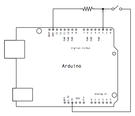
const int buttonPin = 2;
int buttonState = 0;

void setup() {
Serial.begin(9600);
pinMode(buttonPin, INPUT);
}

void loop(){
buttonState = digitalRead(buttonPin);

if (buttonState == HIGH) {
Serial.println("Ojete");
}

}
...with this momentary button (https://www.sparkfun.com/products/11966)

I've managed to use the code successfully with a normal four leg switch. But I'm not sure about the button's connections, any idea? :neutral:
Thanks in advance
By uChip
#177755
Hmmm, the datasheet on the product page shows a two terminal switch so no help there. Same datasheet for the latching version. Reading the comments Robert says the five connections are NO, NC, COM, Anode and Cathode. It shouldn't be too hard to ohm it out. Or you could email SparkFun tech support. They really should include the pinout.

Side note, I see that your code does not do debouncing. If you need to detect individual presses rather than just state, you might want to look at the Arduino Bounce library.

Good luck,
- Chip
By SrBatracio
#177757
Thank you for your answer uChip.

Yes, I checked the datasheet and is not very helpful... more about physical features. About the debouncing, you are right. It is not included because I wanted to check quickly if the button was working as I thought, so I used simple code.

The switch is working, I wired it up properly and it is doing its function, however, I'm not able to do a digital reading with the arduino. When using the regular switch the circuit looks like this...
Image

And I've tried this distribution (beside some more) with the momentary button as it only has two pins...

https://www.dropbox.com/s/p3hfecsvrmtkf9i/ardu.png?dl=0

I hope they help you a bit. Thank you!
By uChip
#177760
Sorry, I'm not understanding you. You said the circuit works with the "regular" button, but not with the two pin button. However the button you referenced has 5 pins. Which is it?

The switch in the diagram above only works because the pins on each side are wired in parallel, but the circuit you link to should be fine with either switch. If it's working with one switch and not the other then you need to carefully check your wiring and the switch pinout.
By uChip
#177761
BTW, you are using a pull-down circuit which might be the problem. A better solution would be to use a pull-up rather than a pull-down. In the pull down circuit the input voltage might drift up if there is any noise or leakage from the input pin. If you pull up instead and have the switch closure to ground the circuit will be more robust. Also, if you switch to the pull-up circuit you can use the internal pull-up on the input which would eliminate the need for the external resistor.
By SrBatracio
#177773
Thank you again for your answer, uChip. I will try out your suggestion with the "pull-up resistor".

About the button, I forgot to tell that the outer pins are just to power the led up. So it should be something like this:
  • C= Common (ground, return path)
    NO= Switched contact, Normally Open
    NC= Switched contact, Normally Closed
    +/- = Power to LED in switch
So I was using only two of them: NO and C.
By SrBatracio
#177787
Hey!

I followed this schema...

Image
and tried again with "Normally open" pin and it worked :)
I'm actually not sure what I was doing wrong.
Thank you anyways.