SparkFun Forums 

Where electronics enthusiasts find answers.

Questions relating to designing PCBs
By DerekPDX
#172776
Hi guys, first off I just want to thank anyone who takes a look at this and provides any assistance. It really is greatly appreciated.

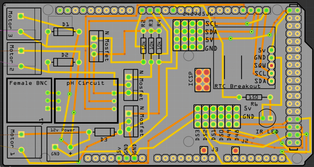
I'm trying to make a custom Arduino Mega Shield to control my aquarium, including running some peristaltic pumps. I think I have almost everything setup right, but I am not sure if the diodes running from the screw terminals where the the motors connect are correct. Are they backwards? Can anyone give me some insight? You can download the fritzing file here: https://www.dropbox.com/s/suu31k4vy3s1q ... quatic.fzz

if you don't want to download it, maybe this picture will be enough:

Image
By n1ist
#172799
The three flyback diodes are backwards. They are supposed to be wired so that they are off in normal operation, so the cathode gets connected to the positive side of the motor, and the anode to the negative.

The traces for power and ground look way too thin for connecting to a motor; you want wide traces to reduce voltage drop.

As far as routing, in general you want traces run horizontally, vertically, or at 45 degree angles. When traces bend, you should use two 45-degree bends instead of one right-angle bend.

You have vias under some of the daughter boards; as long as they can't touch, you are fine, but I would move them given how much space you have.

The 12V power and motor 1 connectors are blocking a screw hole.
/mike
By Valen
#172807
Also the screwhole on the lower right side is touching a track on both sides of the board. The middle upper screwhole is covered by the edge of the GND pins (of the SDA/SCL/5v/GND connector block). The least of the issues however.

The source to ground connections of the N-mosfets seem to merge into a single path to ground/powersource minus (tree topology). With substantial currents running through them it is better to make them run in a star-topology. To avoid different voltage drops from unbalancing the gate to source reference. But as the gate is probably driven digitally this is not likely to be a problem.

However, this will also affect the pH circuit! Turning on Motors 1 and 2 and 3 in different arrangements could raise the ground level of the pH circuit (I assume that connected pin has this function) due to a voltage drop in the combined track to GND on the lower edge of the board. This is not good for accurate measurements!

[EDIT]Looked at the fritzing diagram. Seems the other pins are TX and RX to the Arduino. So no big deal either as they are digital. But it is better to avoid this anyway and learn the right way from the start. In the Fritzing breadboard diagram you have done in the correct topology.
By DerekPDX
#172818
Hey guys, thanks for the advice. I was completely unaware (obviously) that traces shouldn't be made at 90 degree angles. Why is that?

Much of my confusion comes from the fact that I was looking at two different examples of running mosfet diode combination that did it two different ways:

Here: http://fishtankprojects.com/wp-content/ ... -pumps.png

and here: http://bildr.org/2012/03/rfp30n06le-arduino/

So I made different designs based on each:

Image

and:

Image


Here are the fritzing files as well (the old link won't work, that will take you to the old file):

https://www.dropbox.com/s/c88zjirp1n0z3 ... Shield.fzz

https://www.dropbox.com/s/jwhphqnx9n1yw ... dNewer.fzz

Which of these two methods do you think is best?

Also, I made the traces for the motors thicker. That was a good call, and clearly just an oversight. As for the bottom screw terminal covering the screw hole, I am not really worried about that too much. Its just a shield, so its going to stack right on top of an Arduino mega. Its kind of unlikely that someone will need to screw mount it. So the only real issue I think is just a break in the silkscreen drawing for the screw terminal.
By Valen
#172819
In regards to the diode configuration the bottom one seems the good one. Also the Bildr blog link. The top link (fishtankprojects) shows the mosfet sources only to be connected to the Arduino ground. There is no connection shown from the mosfets sources to the powersource minus at all. That cannot work.

The problem I have with your top pcb:
Motor 1 and diode 3 are in series to ground, but the diode is reversed biased. The diode is also parallel to the mosfet. Any voltage spike caused by turning of the mosfet goes through the ground and powersource through the motor to the diode. A much longer path which could potentially do harm in these places. The diode should be across the connections to the motor, NOT across the mosfet drain and source.

You increased the width of the highside powertracks. But the same amount of current has to flow from the mosfet sources through the ground tracks back towards the powerplug. Also on both bords this takes a bypass via the Arduino bord. Yes, they need to be connected to avoid floating levels between the boards. But also care must be taken that it takes the path of least resistance. Thin tracks and connectors do not help with that. If you require an external powersource, make sure the entire current path is contained inside your own pcb.

I also would try to get that BNC and pH circuit away from being surrounded by these motor circuits. I can see that moving the BNC connector elsewhere may be difficult. (other Arduino connectors deny flexibility) But motor turn on/off event could theoretically cause induced spikes. Don't know which currents are running here, but it is a design guideline iirc.
By DerekPDX
#172830
Thanks for the help, Valen, its really really appreciated.

You are right about moving the pH curcuit, and it was something I had been thinking about doing. Not only because the circuits are apparently somewhat finicky, but because the BNC plug is so damn thick it makes it impossible to stack anything else on top of this shield. To correct this, I just made it a little longer and added the BNC plug and the circuit onto the back.

So, here is my revised shield. Let me know what you think:

Image
By Valen
#172831
You still have a mosfet source-to-powersupply ground path that goes via the Arduino pcb. The source of the mosfet for motor 2 goes to the 4th pin on the top row, and to powersupply ground. The sources of mosfets 1 and 3 go only to the gnd pin on the bottom row, 6 and 7 from the left. So these motor currents have to flow through the Arduino pcb to the top ground pin back to the external powersupply. The arduino board is probably rugged enough with a large ground plane. But there could be a trap. You shouldn't expect the Arduino board to take care of high currents that way. Better provide your own ground return paths from the mosfet sources to be sure.

I suspect the tracks from the Arduino to the gates and the (pulldown) resistors do not need to be that thick. There is only so much current that an Arduino pin can provide, or gate capacitance that needs to be charged. But it can't hurt. I don't know how thick is appropriate though.
By DerekPDX
#172832
Its not labeled, but the 4th pin on the top row is common arduino ground. should the mosfet sources and the 12v source all be connected to the same ground pin?
By Valen
#172833
I would keep the ground paths from the mosfets to the powersource grouped together. As that is where they eventually need to go. And less chance of influencing other components by induction. Keep it as short as possible. You also need to connect this powersupply ground to the arduino ground somehow, or else the gates are floating in regards to the sources. But this does not have to be a heavy powerconducting connection.
By Valen
#172838
Yes, that looks ok.

Doesn't the pH circuit board need 5 volt or something like that. I don't see it anywhere, just ground.
By DerekPDX
#172839
YES. Very good call. The bottom left pin of the pH circuit does need a connect to +5v, but turns out the left pin of the BNC plug doesn't need to go anywhere. Thanks for pointing that out. Awesome help, man.