- Sat Sep 21, 2013 1:05 am
#163738
Hey all,
I'm new on here - and to tell you the truth, this is kinda the first work that I've done on Circuit design like this - I've done plenty of wiring over the years on car projects and other things, but never really got down to component level.
So, based on this, I'm hoping that you can all give me some feedback on my design.
I'm building a control box for a small automated system which will be run via an arduino board. However, I also want to add the following capability.
1 - For each Auto Output, I want to be able to choose between On-Off-Auto via a 3 way toggle switch
2 - Show (using RGB LED - 1) whether On-Off-Auto is selected
3 - Show (using RGB LED - 2) whether each Output (to Relay) is switched On or Off (whether via Auto or Manual)
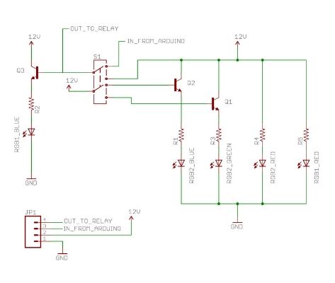
Based on what I've learnt over the past 2 days I've put together this PCB schematic, which I think should achieve what I'm hoping to.

The bottom right corner is the Input/Output Connector
Pin 1 - GND
Pin 2 - 12V In
Pin 3 - Auto Input (12V)
Pin 4 - Output to Relay
The top left corner is the DPDT switch
- First Pole has Auto In and 12 V in, and is used to switch the system between Auto, Manual and Off signal being fed back to the Relay Out and Base pin of Q3
- Second Pole is used to show status, each output is then run to the base pin either Transistor Q1 or Q2
- The 12V In is connected to the Collector of each Transistor, but also to the two Red LED Anode Pins (Via 560 Ohm Resistor a for each)
- The Emitter legs of the transistors are connected to the Blue or Green LED Anode Pins (Via a 470 Ohm resistor for each)
- The Common Cathodes for the LEDS are connected to the GND Pin
I think that should cover almost everything, but if there's anything I've missed, please ask.
Being a n00b I'm grateful for all feedback
Thanks
-
Andy
I'm new on here - and to tell you the truth, this is kinda the first work that I've done on Circuit design like this - I've done plenty of wiring over the years on car projects and other things, but never really got down to component level.
So, based on this, I'm hoping that you can all give me some feedback on my design.
I'm building a control box for a small automated system which will be run via an arduino board. However, I also want to add the following capability.
1 - For each Auto Output, I want to be able to choose between On-Off-Auto via a 3 way toggle switch
2 - Show (using RGB LED - 1) whether On-Off-Auto is selected
3 - Show (using RGB LED - 2) whether each Output (to Relay) is switched On or Off (whether via Auto or Manual)
Based on what I've learnt over the past 2 days I've put together this PCB schematic, which I think should achieve what I'm hoping to.
The bottom right corner is the Input/Output Connector
Pin 1 - GND
Pin 2 - 12V In
Pin 3 - Auto Input (12V)
Pin 4 - Output to Relay
The top left corner is the DPDT switch
- First Pole has Auto In and 12 V in, and is used to switch the system between Auto, Manual and Off signal being fed back to the Relay Out and Base pin of Q3
- Second Pole is used to show status, each output is then run to the base pin either Transistor Q1 or Q2
- The 12V In is connected to the Collector of each Transistor, but also to the two Red LED Anode Pins (Via 560 Ohm Resistor a for each)
- The Emitter legs of the transistors are connected to the Blue or Green LED Anode Pins (Via a 470 Ohm resistor for each)
- The Common Cathodes for the LEDS are connected to the GND Pin
I think that should cover almost everything, but if there's anything I've missed, please ask.
Being a n00b I'm grateful for all feedback
Thanks
-
Andy
