SparkFun Forums 

Where electronics enthusiasts find answers.

For the discussion of Arduino related topics.
By SourcePatrol
#157398
Hello, and nice forum!

I'm new to the Arduino and electronics in general... and at this point the only experience I have is completing a SparkFun Starter kit... :oops: so please excuse my lack of knowledge.

Basically, I want to control a valve with my Arduino for a science project I'm working on with my sons. Here are the specs on the valve:

Voltage Range: 0-10 vdc
Power Consumption: 1.9 watts, 2.3 watts max
Response Time: 3 to 5 ms

Circuit:
Does anyone know of some examples or tutorials for a similar solenoid operation? (most solenoid examples I've found are for simply turning the valve ON or OFF, and this is not what I want) I would like to proportionally open and close the valve with a Potentiometer I have... If that will even work.
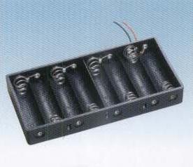
Power:
I want to power the valve with a battery... and weight is my biggest concern. I only need to power the valve for 1 minute or less.
Does anyone have any suggestions for a lightweight battery setup for the valve in question?
Should I use a separate battery for the arduino?

Any pointers would be appreciated. I understand more learning is ideal and I certainly plan to keep it up... but I'm also anxious to get the valve at least working.
Last edited by SourcePatrol on Mon Mar 25, 2013 1:34 pm, edited 1 time in total.
By waltr
#157410
You could use a filtered PWM output from the arduino to generate a variable voltage (current) to control the valve. This would need a current boost (the arduino output is only about 20mA) using a transistor.
By Mee_n_Mac
#157414
SourcePatrol wrote:Any pointers would be appreciated. I understand more learning is ideal and I certainly plan to keep it up... but I'm also anxious to get the valve at least working.
Look at the Circ-03 tutorial in the SIK Manual.
https://www.sparkfun.com/tutorial/AIK/A ... AR-WEB.pdf
While it's driving a motor, the same circuit (has 1 error) will work for your proportional valve as it does for the motor and is what waltr mentioned. The error in the schematic is the base resistor. They list it as 10k ohms; it should be more like 220 ohms for both the motor and your valve (the current draw is about the same for both). You could run your valve off a 9V battery, so use 9v where you see 5v in the diagram for Circ-03. An alkaline battery, with a capacity over over 500 mA-hr should last a bit over 2 hrs. A disposable lithium would last quite a bit longer.
By SourcePatrol
#157423
Mee_n_Mac wrote:
SourcePatrol wrote:Any pointers would be appreciated. I understand more learning is ideal and I certainly plan to keep it up... but I'm also anxious to get the valve at least working.
Look at the Circ-03 tutorial in the SIK Manual.
https://www.sparkfun.com/tutorial/AIK/A ... AR-WEB.pdf
While it's driving a motor, the same circuit (has 1 error) will work for your proportional valve as it does for the motor and is what waltr mentioned. The error in the schematic is the base resistor. They list it as 10k ohms; it should be more like 220 ohms for both the motor and your valve (the current draw is about the same for both). You could run your valve off a 9V battery, so use 9v where you see 5v in the diagram for Circ-03. An alkaline battery, with a capacity over over 500 mA-hr should last a bit over 2 hrs. A disposable lithium would last quite a bit longer.

Thank you.
By SourcePatrol
#157602
Ok... i'm still having some issues... and am kinda lost.

I want to control this valve with a Potentiometer (I have two linear pots ... one is a 6k and the other is 10k.. not sure if I can use either of them)

I've successfully hooked up a DC motor to a potentiometer with the parts seen here: http://luckylarry.co.uk/arduino-project ... -supplies/

but this is not what I need... I need to control the current somehow..

Is there anyway to use a similar circuit/code to control this valve?

This page has more information: http://www.kpiwebsite.com/applications.html#ValveApp
By Mee_n_Mac
#157604
You are controlling the current. You are switching it from full on to full off to full on ... etc, etc at about 500 times/sec. If the on/off waveform spends 50% of the time commanding on and thus 50% commanding off, the valve can't react, can't open and close, that quickly. So it averages and goes the half open position. If the waveform spends more of it's time commanding open than closed, then the valve goes to a more open position. The valve is not really any different from the motor.
http://arduino.cc/en/Tutorial/PWM

You could use either pot, the 10k would be my choice because I like the number 10 more than 6.

There's one thing that bothers me a bit though. You listed a "response time" of 3-5 msec. That seems pretty fast. The graph at the bottom of your link shows a response time that's more like 300 msec but it may not be generic. Do you have more data from the vendor on your particular valve ?
By SourcePatrol
#157605
Mee_n_Mac wrote:You are controlling the current. You are switching it from full on to full off to full on ... etc, etc at about 500 times/sec. If the on/off waveform spends 50% of the time commanding on and thus 50% commanding off, the valve can't react, can't open and close, that quickly. So it averages and goes the half open position. If the waveform spends more of it's time commanding open than closed, then the valve goes to a more open position. The valve is not really any different from the motor.
http://arduino.cc/en/Tutorial/PWM

You could use either pot, the 10k would be my choice because I like the number 10 more than 6.

There's one thing that bothers me a bit though. You listed a "response time" of 3-5 msec. That seems pretty fast. The graph at the bottom of your link shows a response time that's more like 300 msec but it may not be generic. Do you have more data from the vendor on your particular valve ?
Thank you for your time. Here is the specific page for my valve: http://www.kpiwebsite.com/docs/MPVspec.pdf

So are you saying I can control this valve with the same circuit/code found here?: http://luckylarry.co.uk/arduino-project ... -supplies/
This is the same thing as the example you showed me right?
By Mee_n_Mac
#157607
SourcePatrol wrote:So are you saying I can control this valve with the same circuit/code found here?: http://luckylarry.co.uk/arduino-project ... -supplies/
In a word ... yes. But that response time spec bothers me. IF it's to be believed then the valve may actually (partially) mechanically respond to the 2 msec waveform from the Arduino. The valve may "flutter" about the desired position. You might get the same end result but now the valve is being exercised and it's lifetime reduced accordingly. Perhaps an e-mail to the vendor asking him about PWM control and a min frequency would be a good idea ?

You can change the PWM frequency to be higher and so out of the mechanical response range.
http://arduino.cc/en/Tutorial/SecretsOfArduinoPWM
http://playground.arduino.cc/Main/TimerPWMCheatsheet

Or use some other external circuit but I'd contact the vendor first.
By SourcePatrol
#157613
Mee_n_Mac wrote:
SourcePatrol wrote:So are you saying I can control this valve with the same circuit/code found here?: http://luckylarry.co.uk/arduino-project ... -supplies/
In a word ... yes. But that response time spec bothers me. IF it's to be believed then the valve may actually (partially) mechanically respond to the 2 msec waveform from the Arduino. The valve may "flutter" about the desired position. You might get the same end result but now the valve is being exercised and it's lifetime reduced accordingly. Perhaps an e-mail to the vendor asking him about PWM control and a min frequency would be a good idea ?

You can change the PWM frequency to be higher and so out of the mechanical response range.
http://arduino.cc/en/Tutorial/SecretsOfArduinoPWM
http://playground.arduino.cc/Main/TimerPWMCheatsheet

Or use some other external circuit but I'd contact the vendor first.
Ok thanks, I just emailed the vendor asking about pwm and min frequency... hope they get back to me.

So what you are saying is that the default waveform from the Arduino is taking 2ms but I may need to increase that because the valve does not have time to catch up?

I hooked up the circuit and using power from a fresh lithium 9volt, I still could not get the valve to work... I heard a small hum and that's it.

This is the code I'm using and it's working fine for a dc motor.
Code: Select all
int potPin = 0;                           // Analog pin 0 connected to the potentiometer
int transistorPin = 9;                  // connected from digital pin 9 to the base of the transistor
int potValue = 0;                       // value returned from the potentiometer

void setup() {                          // set  the transistor pin as an output
  pinMode(transistorPin, OUTPUT);
}

void loop() {                           // read the potentiometer, convert it to between 0 - 255 for the value accepted by the digital pin.
  potValue = analogRead(potPin) / 4;    // potValue alters the supply from pin 9 which in turn controls the power running through the transistor
  analogWrite(9, potValue);
}
By Mee_n_Mac
#157621
Hmmm, a "9"v battery really isn't 9v but I thought the Li would supply the <200mA w/o dropping too much voltage. Could be that's just not the case. If it works for the motor and not the valve and the wiring is double checked then the battery is just too weak for this case. You could try to find a 10V wallwort (that's something of an odd voltage) or build your own "10v" battery from AA (or other) cells. 8 rechargable NiMh cells in series (like using 2 of these in series) gets you 10V. You can buy 8xAA battery holders but there's no reason you couldn't make on yourself that would look like a crude version of this.
Image

FWIW you want to increase the frequency of the Arduino's PWM which will shorten the time it takes the Arduino to repeat the PWM waveform. That way the on/off/on/off... pulses happen so quickly that the valve can't mechanically move to follow each on/off command, and the pulsed current through the coil will produce a force that's proportional to the average of the on/off times. That way the valve doesn't mechanically flutter (much), it just goes to the position you want. Something that repeats 500 times/sec takes 2 msec to do 1 cycle. Something that repeats 1000 times/sec takes 1 msec to do 1 cycle.

If I may ask, how many $$s was it for that valve ? It just seems very fast (to me) for the kind of $$s I'd expect to spend for a science project.
By SourcePatrol
#157623
Mee_n_Mac wrote:Hmmm, a "9"v battery really isn't 9v but I thought the Li would supply the <200mA w/o dropping too much voltage. Could be that's just not the case. If it works for the motor and not the valve and the wiring is double checked then the battery is just too weak for this case. You could try to find a 10V wallwort (that's something of an odd voltage) or build your own "10v" battery from AA (or other) cells. 8 rechargable NiMh cells in series (like using 2 of these in series) gets you 10V. You can buy 8xAA battery holders but there's no reason you couldn't make on yourself that would look like a crude version of this.

FWIW you want to increase the frequency of the Arduino's PWM which will shorten the time it takes the Arduino to repeat the PWM waveform. That way the on/off/on/off... pulses happen so quickly that the valve can't mechanically move to follow each on/off command, and the pulsed current through the coil will produce a force that's proportional to the average of the on/off times. That way the valve doesn't mechanically flutter (much), it just goes to the position you want. Something that repeats 500 times/sec takes 2 msec to do 1 cycle. Something that repeats 1000 times/sec takes 1 msec to do 1 cycle.

If I may ask, how many $$s was it for that valve ? It just seems very fast (to me) for the kind of $$s I'd expect to spend for a science project.
The valve was around $60... I was on a valve hunt for days before I found this one. We are making a water rocket engine to be used on a small rc car and maybe other things.

The same company that makes this valve also has a driver board: http://www.kpiwebsite.com/products-DrvBrd.html

I'm considering buying the driver board to use with the arduino but it requires 12vdc...

I contacted the company and also asked about the driver board.. and here's what I got back:

"The driver board may be a great way to use micro controller to amplify the current to the valve. The driver board can use the control signal from the PWM controller, and amply the necessary current, but it would need to be used with a 12 volt power supply, since you have a 10 volt coil valve. Would you have access to a 12 volt power supply voltage? Your valve will need 180 milliamps, so the power supply would need to handle this.

Regarding the PWM from your contoller: The typical range of PWM hertz is a minimum of 500 hertz, and as high as 10,000 hertz. This makes sense, since the response time is limited to 2-3 milliseconds.

As far as the response time, we have had the mini valve react as quickly as 2 milliseconds from fully closed to fully activated. The response time will be affected some by using water, and if you have any back pressure on the valve, but you may find the valve reacted in your application in 3-5 milliseconds. This is a measure of fully open to fully closed, so smaller changes in the control current may be faster."

The driver board is $$ and I guess that kills my plan to use a 9v... I really need this to be lightweight and not so many batteries!

Any advice? I feel like I should compensate you for all the help! gotta paypal? :-)
By Mee_n_Mac
#157629
Their driver board looks to be a fancier version of what you've already done. It just takes a variety of different types of inputs and will control both their 12 and 24 V products. But it does use PWM to do it. And I'd definitely increase the PWM speed if the fully open to close time is in the range of 3-5 msecs. For the moment, let's put that aside, it's just a matter of software that I've not done so haven't figured out yet.

Now that I know this is on an RC car ... what batteries power/voltage do you have to run the motors that are (?were?) on that car ? I'm guessing there's a fair amount of power to run any car that would carry this valve. Or is this a brand new design, all of your own ? Given the $$s you've put into it, a LiPo and the associated charger may be a good fit. Look at the LiPo batteries that even just SF sells. Let me go over some options, starting with the "worst" and going to the "best".

This battery is waaaay overkill for your current draw but it's a start. It's really 3 LiPo cells in series (3 x 3.7v = 11.1v). Don't worry about the voltage ATM, making higher voltages into lower voltages is easy.
https://www.sparkfun.com/products/10470

You could use 3 of something like this. Put them in series and it's the same 11.1V (nominal) but less current capability and smaller (overall) size and weight. It can (just!) output enough current to operate the valve at full open and only do so for 30 mins (full open, 1 hr at half open, etc, etc). It probably represents the smallest you could go.
https://www.sparkfun.com/products/731

LiPo's pack a lot of energy and power into a small package and so you have to use more caution when using them and charging them and storing them. They are the standard battery in RC planes for the size and weight reasons. The same rationale may make them the best battery (technically) for your rocket car. You can no doubt find a wider variety of LiPos in the 3-cells-in-series (3S), 11.1 V configuration shopping at some RC sites/places. You'll need a LiPo charger as well and read up on "balancing" LiPo cells while charging and the cautions when using them. Google for LiPo safety, tips, charging, etc and I'm sure you can find all manner of instruction on their care and feeding.

A typical LiPo cell will be 4.2V when fully charged and drops in voltage as it gets used. They are considered to be "empty" when the voltage gets down to about 3V or so. At the low currents you'll be drawing from the cell you could either use a low drop out (LDO) voltage regulator to get the 11+ V down to 10V or perhaps just add a diode in series with the battery output to drop 0.7V from the pack's voltage and call that close enough.

I've saved the best (mebbe) for last. You could use a single high current LiPo cell (3.7V nominal) and use a step-up voltage regulator to make 10V from it's 3.0 - 4.2 V. Given your current draw is low (200 mA max) this might be a very good match-up, probably unbeatable for weight and size. 10V @ 200 mA is 2W. Assume a poor efficiency of 70%. That means the LiPo must supply 2.9W, let's call it 3W. At 3V that's 1A and so a single cell LiPo (3.7V nominal) rated at 1000 maH (that's 1000 mA, 1A, for 1 hour) should do the trick. And all you'd need is a basic single cell LiPo charger.
Battery:
https://www.sparkfun.com/products/339 or 1 step larger for a longer runtime btw chargings
https://www.sparkfun.com/products/8483
As for a boost converter/ step-up, people have thought highly of these (I've not used one):
http://www.pololu.com/catalog/category/132
http://www.pololu.com/catalog/product/799
I note that there's a 12V (fixed, non-adjustable) version if you want to use the valve vendor's driver board.
By SourcePatrol
#157665
Master Mee_n_Mac, thank you for helping me (and everyone else on here).

I like the idea of using the step-up voltage regulator and will give it a try!

We are still in the early stages of this project and really just learning as we go. I'm working on the plumbing first and then will move onto the other aspects.

I tried the 8 battery series you suggested with my same circuit... but the valve only opened a little bit (i also tried it with a little pressure)... and this was with the POT almost all the way.

So... I'm leaning towards getting the driver board from the vendor as they will give me a discount... just to make things easy.

I still want to use the Arduino and the only other hardware i need to control is 2 small servos (for now)... and I can power these easy.

So I should be able to just hook up the pwm pin on the Arduino to the input on the vendor driver board, and it will work? still need to change freq? I guess i'm just kinda lost on how that would work... being that I don't really understand the flexibility or interworkings of this driver board.

I think the power should be fine with your recommended setups. Thanks again.
By Mee_n_Mac
#157669
SourcePatrol wrote:I tried the 8 battery series you suggested with my same circuit... but the valve only opened a little bit (i also tried it with a little pressure)... and this was with the POT almost all the way.
Well that's a bit disturbing ! This bears further investigation. Did you measure the voltage out of the battery pack ? If not, measure it. Quite frankly anything above 9V should work well enough. If the voltage is OK then connect the battery directly to the valve. See if it works then. It should. If it doesn't then your valve would appear to be faulty.

If the valve works w/a direct connection then your driver circuit or software is suspect. Eliminate the analogWrite() to the driver pin and just do a digitalWrite(). Measure the (now constant) voltage at the Arduino output. It should be > 4.5V. See if the valve is full open then. If it is then post your code, there's something goofy therein. If the valve still isn't open then check the "10V" at the valve + terminal and the voltage at the valve - terminal. We'll take it from there. But if the 10V is present and the - terminal isn't < 0.2V then somethings goofy with your circuit.

It's fairly common to think everything is right with a simple transistor circuit but until you measure it to be right ... assume it isn't. It's just too easy to make a simple wiring error and then not be able to "see" it. It's like proofreading your own writing. You know what it's supposed to be and dammit, it's right ! :mrgreen:

BTW interesting rocket car project. I want a YouTube link when it's done ! 8-)
By Mee_n_Mac
#157670
SourcePatrol wrote:So... I'm leaning towards getting the driver board from the vendor as they will give me a discount... just to make things easy.

I still want to use the Arduino and the only other hardware i need to control is 2 small servos (for now)... and I can power these easy.

So I should be able to just hook up the pwm pin on the Arduino to the input on the vendor driver board, and it will work? still need to change freq? I guess i'm just kinda lost on how that would work... being that I don't really understand the flexibility or interworkings of this driver board.
Two additional points. You should look to power the system in the best overall way. IIRC SF sells a combo step-up converter to 5V (is your Arduino 5V ?) and single cell charger BoB. Two birds, 1 BoB. You could split your LiPo output into both the 10V step-up and the 5V step-up. But be wary, servos can draw a lot of current. Somewhere I posted a link to some servo tests where the guy measured the current draw for a large number of servos. I hope I saved the link, will post it if I did. In any case the BoB may, or may not, be able to supply the current needed for the Arduino and 2 servos.
Test results of servo current draw:
http://homepages.paradise.net.nz/bhabbott/Servo.html

As for the driver board ... do the troubleshooting in the prior post 1'st. From what the vendor said, his board should play nicely with the Arduino. The 0-5v, 0-10v and current loop interfaces are all common standards for PWM control. I'll bet the 0-5, 0-10 input are also proportional analog voltage control inputs as well. So I have no reason to question the vendor's judgement in this regard. I'm not sure why it's would need 12V to run the 10V valve but that's not a practical drawback.

As for increasing the Arduino's PWM frequency from 500 Hz to ??? Yes, I think that wise. Your valve is fast (IMO). You will have some mechanical flutter at 500 Hz. Might as well avoid the wear and tear if you can. The only drawback is that messing with the timer that sets the PWM freq also messes with some other common Arduino functions ... maybe one you use (servo commands). But there's ways to fix that so long as you're aware of the functions impacted. No big deal IMO.