SparkFun Forums 

Where electronics enthusiasts find answers.

Have questions about a SparkFun product or board? This is the place to be.
By edward.ford
#85705
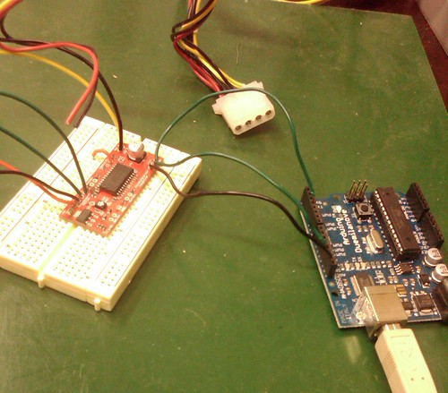
I'm trying to get an 8 wire stepper motor hooked up to the easy driver v4. Here's the story.

After pouring over tons of web pages and trying to figure out exactly how steppers work, I think I’ve narrowed it down to three possibilities. However, I have no idea if I’m correct. For all I know, this could be completely wrong. If anyone knows the right way to do this *PLEASE* let me know.

Overview:
I turned my mulit-meter so when I touch the two probes together, they beep. (continuity mode?)
Then, I went through all the pins, and this is how they line up:
Pin 1 + Pin3 = Beep
Pin2 + Pin4 = Beep
Pin5 + Pin7 = Beep
Pin6 + Pin8 = Beep.

Option1: Take one wire from each pair, twist them together and connect all 4 of them to M+, use the other 4 wires to connect to A,A,B,B on the EasyDriver

Option2: Twist the pairs together, connect the 4 pairs to A,A,B,B on the EasyDriver

Option3: Take one wire from each pair, do not connect to anything, take the other 4 wires and connect to A,A,B,B.

As you can tell, I’m a complete noob, so seriously any help, as rudimentary as it may seem to you, would be greatly appreciated.

Thanks in advance,
Edward
By emf
#85719
You're off to a good start, but we still don't have enough information to know which wires to connect to which. I'm pretty sure none of your three options will make a motor spin.

Piclist has a nice page on how to figure out which wires are which here -- scoll down to the procedure starting with "8 Wires:".

If you happen to have a datasheet or other information about the motor, we might be able to figure it out from that.
By edward.ford
#85721
emf: Thanks for the reply! I'm really excited about seeing these things work!

I looked up the motor and there is indeed a spec sheet! However, I'm so green I don't even know what I'm looking for....http://www.alltronics.com/mas_assets/acrobat/28M060.pdf

Looking at the bottom of the page in the section titled: "Lead Wire Connection" That appears to be what I had figured out for my pinouts!

But What does the bottom part mean? It's confusing because I only see "As and Bs" but the pinouts have A,B,C,D? I'm guessing the blue underlines are a clue, but I can't figure those out...

What am I missing?

Also, here's a good picture of my actual motor: http://www.flickr.com/photos/edwardford ... 134310283/
User avatar
By phalanx
#85731
From your first post I could not figure out what you meant by pins 1-8 because the picture of the EasyDriver board looks like this:
Image

I'm going to assume that this is the board you are working with. This board is designed to drive Bi-polar stepper motors which typically have 4 wires coming from them. The good news is an 8 wire stepper can be wired to be compatible with this driver. First we need some more details. I wandered over to the Lin Engineering website and was able to get much more information than what all-electronics supplied. This picture shows the coil arrangement inside your stepper.

Image

Because your motor has 4 coils, but your driver is only expecting 2, we need to combine them. This can be done by either wiring the pairs of coils in parallel or series. Which configuration depends on how you want your system to operate. In a series connection you will need a higher voltage at a lower current to get the desired torque out of your motor. In a parallel arrangement, you don't need as much voltage but you will need more current from the driver. The lower inductance of parallel winding allows for greater torque at higher speeds while the opposite is true for series wiring. Since this is a size 23 stepper motor and the driver can only source up to about 750mA, I'm guessing you will want the series wiring arrangement.

For reference, this is a generic graph of speed vs. torque for series and parallel wiring:
Image

Since we are interested in series wiring for a bi-polar driver, have a look at the following chart from the Lin Engineering website (8-wires; Color Code 1; Bipolar Drive Series Connection):
Image

What this chart has you do is:
Connect red/wht with blu
Connect blk/wht with grn
Connect blu/wht to the leftmost "A" on the driver board.
Connect red to the rightmost "A" on the driver board.
Connect grn/wht to the leftmost "B" on the driver board.
Connect blk to the rightmost "B" on the driver board.

After making the rest of your connections, you should be able to drive your stepper motor.

If you need more help, feel free to ask.

-Bill
Last edited by phalanx on Mon Nov 23, 2009 7:18 pm, edited 1 time in total.
By emf
#85733
The company that makes your motor has a nice PDF on how to connect their motors here. They show two ways of connecting the motor: bipolar drive parallel connection; and bipolar drive serial connection. You can use either method. If you choose the parallel connection, you'll get better torque at high speeds. If you choose serial, you'll get better torque at low speeds.

[edit]phalanx beat me to the punch with a much better explanation that I gave. do what he says :-)
By edward.ford
#85737
@emf & phalanx: Thank you both for your help. I feel pretty silly for not checking the lin website now.... Although to be honest I don't think I would have figured it out without the explanation.

I will give this a try when I get home tonight and see if I can get my Arduino to spin the motor.

My plan is to use an old ATX power supply (12vDC @ .7A) to test the setup. Do you guys see a problem with that?
By EmbeddedMan
#85743
Nope, I use 12V from PC power supplies all the time - many people do because they're so cheap.

*Brian
By edward.ford
#85744
Awesome! OK, will post back with some results. Thanks again everyone. You've made my day.
By edward.ford
#85827
This my first attempt at a schematic, so again, go easy.

Image

I have four questions.

1.) Can I put all of the GND to the Power Supply GND or does the GND that goes with +5v on the ED have to go to the Arduino Ground?

2.) Why is "M+" denoted as such? I've never seen that before. I have seen it as Vcc or a noted voltage such as +5v. Just curious what the differences are.

3.) What program do people commonly use to draw schematics?

4.) Can anyone recommend a really good beginners electronics book? Something that would go over the basics of electricity and get me feeling a little more comfortable with the 101 stuff.
User avatar
By phalanx
#85831
edward.ford wrote: 1.) Can I put all of the GND to the Power Supply GND or does the GND that goes with +5v on the ED have to go to the Arduino Ground?

2.) Why is "M+" denoted as such? I've never seen that before. I have seen it as Vcc or a noted voltage such as +5v. Just curious what the differences are.

3.) What program do people commonly use to draw schematics?

4.) Can anyone recommend a really good beginners electronics book? Something that would go over the basics of electricity and get me feeling a little more comfortable with the 101 stuff.
1. The schematic for the ED shows that all GND locations are the same so you could ground the Arduino at the power supply. I'd keep it connected to the ED though for the time being.

2. M+ is simply the choice of the board designer. I'm sure he meant to associate M+ with with positive motor voltage.

3. I typically use Eagle PCB which is a circuit board designing application that is quite popular because it has a free version. Your schematic is easy to read so whatever you used is fine too.

4. Someone else will have to help you with this. I'm way out of touch with what constitutes a good entry level electronics book.

-Bill
User avatar
By phalanx
#85832
You may want to tie into the MS1 and MS2 pins which will allow you to experiment with microstepping and how it effects the performance of your motor. Internally to the ED, they are pulled high through a pull-up resistor. If you pull them low with your controller you can toggle between full, half, quarter, and eighth steps.

-Bill
By EmbeddedMan
#85836
Yup, I chose M+ because MOTOR_POS just wouldn't fit. :-)

Seriously, I didn't want to put Vcc because that's not what it is - it is the unregulated (6V to 30V) power input. There isn't enough room to put "6V to 30V DC Positive" or anything that descriptive. You figured it out, so it must have worked. <grin>

My only concern with what you're doing is the current draw of the Arduino. it will be pulling 5V from the ED, which is fine, as long as the ED's 5V regulator doesn't overheat. So keep an eye (or finger) on it to see if you're pulling too much current.

Also, you only need one GND connection from the Arduino to the ED.

Also, very nice schematic! I wish I had diagrams that clear on the EasyDriver website. Sweet.

*Brian
By edward.ford
#85852
@EmbeddedMan: This is where I fail epically: Why is the arduino pulling 5V from the ED? I thought the arduino was getting it's 5V from USB and giving 5V to the ED? Although I can't figure out why the ED would need +5v from the Arduino... Oh wait...I don't need to hook those wires up if I'm using USB! Right?

@Phalanx: Thanks for the tip! I'll add those two pins into the arduino and see how the motor stacks up in different configurations.

Hopefully I'll get time tonight to put this together and see if it works!
By EmbeddedMan
#85858
Sorry, the only failure was that there is no USB cable shown in the diagram. I had assumed that there was no USB connection to the computer, because it is not shown.

You are %100 right - if you are powering the Arduino via USB, then you should NOT have the 5V line connecting to the EasyDriver.

*Brian
By edward.ford
#85879
The Awesome News: It worked! Here's a picture of the setup.

Image

The not so awesome news: I was so excited after the motor ran, that I hooked one up to the Y axis on my newly built CNC machine: It worked! Then stalled. Then worked! Then stalled. Then worked! It made a really unsettling vibrating noise when it was stalling, sounded like my whole machine was going to come apart!

Right now I'm only using 12v from the ATX power supply. Would using more Volts make a difference? I guess I'm wondering if the motor could produce more torque which might prevent the stalling, if it had more Voltage .

Or would the ED need more current to produce more torque? If that's the case, how do I get more current? Could I tie two 12v DC ATX power supplies together in series?