SparkFun Forums 

Where electronics enthusiasts find answers.

Questions relating to designing PCBs
By chabboud
#76345
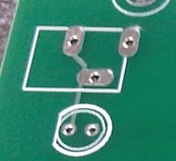
DC Barrel Power Jack
(http://www.sparkfun.com/commerce/produc ... cts_id=119)

This jack has three flat prongs but the Eagle library produces circular holes that are too small. Is there any way to make an elongated-through hole in Eagle to match the prongs?

Is there an actual problem with the Eagle library or am I doing something incorrectly? (I am still new at this.)
User avatar
By leon_heller
#76347
You need to ask the board supplier to rout the holes, or use chain drilling. Some manufacturers don't like the latter, though.

Leon
By chabboud
#76477
hmm. I don't remember getting that option when I submitted the gerbers to PCBExpress. I guess I will just make the radius bigger next time.
By Philba
#76478
what's wrong with the holes? They work fine for me.
By chabboud
#76481
This was the result of my attempt.

Image

This is the part.

ImageImage
By Philba
#76527
hard to tell from the picture but the holes may simply be too small. You should always print out the PCB for a dry-fit test before you commit to FR4. That problem would have shown up then. I have a number of library parts for similar kinds of connectors - just make the holes big enough for the tabs.

You can rescue that board by taking a dremel to the tabs on the part. ugly but saves a round trip to the pcb factory.
By chabboud
#76548
I eventually found this in the EAGLE manual.
8.11 Components with Oblong Holes

If the board manufacturer have to mill oblong holes, you have to draw the
milling contour of oblong holes in a separate layer. Usually this is layer 46, Milling.

The milling contour for components that need oblong holes can be drawn
with WIRE (and possibly ARC) with a very fine wire width near or even 0 in the Package Editor. Take a pad that has a drill diameter which lies inside the milling contour, or SMDs, for example in Top and Bottom layer, as basis for the oblong hole.

In case of a multilayer board you should draw a WIRE in the used inner
layers at the position of the oblong holes so that it covers the milling contour and leaves a kind of restring around the opening.

Please inform your board manufacturer that they have to take care on the
milling data drawn in this layer. Also tell them whether they should be
plated-through or not.
So Leon was correct. I checked that part again and there is data in Layer 46 for elongated holes.

I don't think PCBExpress offers this service, though.
User avatar
By leon_heller
#76579
If it's a prototype you could simply use large round holes, and fill them with solder. I do that and it works OK, but I wouldn't do it with production boards as the solder might fracture with repeated insertions of the connector.

Leon
By jaycollett
#79739
I noticed this on a board I was building. You need to use the other power jack part in the SFE library with large round holes for prototyping.