SparkFun Forums 

Where electronics enthusiasts find answers.

Tips and questions relating to the GPS modules from SFE
By noceco33
#45590
Hi everyone:

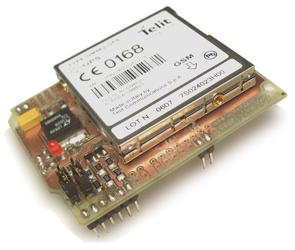
Im making my final thesis with a GPS-GSM Module (model GM862-GPS from Telit) builded inside a board to be plugged into a Arduino (amazing arduino!!).

This is the GM862-GPS builded into a specific board for Arduino

Image

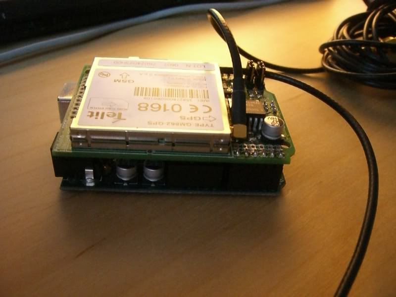
And this is my device together.

Image
Image

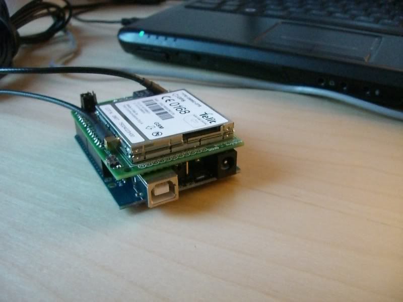
As you know, the arduino communicate with the computer by a USB cable, but the arduino drivers emulate a serial port. I think that my problems are here, becouse with a serial terminal (arduino bootloader have one, but I check another two) I try to send AT comands but I don´t have any response. I also check the arduino without the GM862 module, and it works fine, That means than I can upload with the emulated serial, code from my Laptop to the micro Atmega168 and it works.

So, the problem is when I plug the Telit to Arduino board, I swich on (two seconds pressing the button) the led is lighting and start sending comands trought the serial terminal, but nothing!!!

And I check different rates (baud) 4800, 9600, .., 115200, almost all of them, and diferents flow control. With some of that rates sometimes (when I change some config in the com3 hardware setup) the response can be the same sentence I write or stranges caracters, if that is a response!!!

I don´t know what can i do now, tomorrow, im going to try with an osciloscope, cos maybe the GM862, don´t send anything to the arduino.

PLEASE HELP!!!! hehe

Thanks for your time if you have been read all, and sorry about my english

Bye
By noceco33
#45596
Ok I just make de device awser me!!!!
So the communication is ok, but testing simple commands like the software shutdown, AT#SHDN<CR>

the response is "error"

Someone knows why????

Thanks again
By incognico
#45738
Does AT+GMI confirm that you're actually talking to the Telit module?
By dan_lake
#46763
Hi...I have similar problems to this...I have the same GPRS/GPS shield as this one and I am trying to make Arduino send SMS messages...but cannot get any response from the module.

How did you get it to talk back to Arduino??

Thanks
Dan
By noceco33
#47230
To comunicate, with this module, I mean, to send directly At-commands, to it, don´t use Arduino serial terminal, download one better, and take out the Microcontroler.

Cos to send a command, for Example "AT+CPIN=1234" (to set up the pin code of the SIM card), you shoud write what I put into the comas, then CR (press intro) and then send that (with the mouse i.e.).
Cos if you press intro with Arduino serial terminal, you are allready sending the comand but no the Carrier return (CR).

But if you want to send AT commands to the GM862, thougth the microcontroler, (with C code for arduino), and your module is from Libelium company, you should change the possition of the 2 jumpers that apears in the second and the third picture. That allow to comunicate the module with the micro, and not with the UART USB serial.
By java
#49003
I have same problem, the communication between arduino and gm862.
I can send AT command from hyper terminal but I can not when I use Serial.println("AT"); . I need help as soon as possible.

if any one help me it will be great favor.
By noceco33
#49005
It depends the module that is in betwen the arduino and the Gm 862, becouse in my case im using the Libelium company device for arduino which have two jumpers, when this jumpers are (both) in the down possition the Gm862 module only comunicate with arduino usb serial chip, and in the other possition the module comunicates with the arduinos microcontroler

I had that problem some moths ago!!

Good luck
By java
#49023
thank you for your cooperation. I also use the same board and I set the jumber to enable the communication between arduino and libelium board but the problem still there.

Can you send me the code you write to send AT command pleas? Because I want to compare it with my code
By noceco33
#49025
Im sorry Java, but I cannot send my code cos Im developing a system for a Company, but I think i can help you,

When you plugg the Gm-862 (libelium) board over arduino, the GPS part of the module connects with the arduino via digital pin 2 for RX and pin3 for TX, and the GPRS communication with digital pins 0 and 1, and that are the USB-Serial communications (UART).
I mean, that you can send the AT commands and the Telit take it, but you can't read the answer in the terminal. cos is used by the GPRS.

Try with this

Serial.print("AT+CPIN=1234");

put instead of 1234 your Pin code, and have a look to the green led of the module, if after some seconds start lighting with less frequency, it means that you insert correctly the pin code and you have coberture

So, you can read in the terminal the Serial.print but not the answers.
By java
#49429
int onModulePin = 5;
void setup(){
pinMode(onModulePin, OUTPUT);
digitalWrite(onModulePin,HIGH);
delay(2000);
digitalWrite(onModulePin,LOW);

Serial.begin(38400);

}

void loop(){

Serial.println("AT+CMGF=1");
delay(1500);
Serial.println("AT+CSCA=+9********");\\
delay(1500);
Serial.println("AT+CMGS=+9********");
delay(1500);
Serial.println("HI");
delay(1500);
Serial.println(26,BYTE);
}


this is the code I used but when I upload the code to arduino and connect gm862 to it I do not rescive any sms.
can you help please
By noceco33
#49599
I didn't check to receive a SMS. sorry

Serial.println("AT+CSCA=+9********");
In my case this is not necesary, because the number os the incomin networt server is automatic.


and to send the SMS try to put this

Serial.print("AT+CMGS="); //AT comand to send SMS
delay(300);
Serial.println("+3**********"); //Print the Tel number

For me it works.

But you don't introduce the PIN code of your SIM card. right?

Serial.print("AT+CPIN=1234");
delay(4000);

The green light should change the lighting frequency when your Telit module take a network signal.
By noceco33
#49600
and change the

Serial.begin(38400);

to a 9600 value, is more normal, the Telit standard works at 4800, but in my case I put 9600 and any problem
User avatar
By AZRobbo
#58429
Hi noceco33,

It appears that the shield you have is no longer available, so I am trying to re-create one. I have the Schematic from the links in your posts, but some additional pictures of the board would really help.

If possible can you post a picture of the top of the board (with the module removed), and a picture of the bottom of the board (without the Arduino connected).

These pictures will really help me understand the jumper configuration (which is a little confusing right now).

Thanks, and let me know if you have problems posting the pictures, and i'll send you my email address.

Cheers,
Rob.
By noceco33
#58454
Sorry I cant help you, cos Im not in that project anymore.. but you can find that in www.arduino.cc
User avatar
By AZRobbo
#58468
Thanks for the quick reply. Unfortunately, I've scoured the arduino.cc forums, and performed many Internet searches and found very few pictures of this shield.

Your pictures at the top of this thread are the best ones that I've found so far.