SparkFun Forums 

Where electronics enthusiasts find answers.

Questions relating to designing PCBs
By jandirks
#36980
Probably I am doing something wrong (due to lack of knowledge of the software I am using), but I have some troubles (again) getting my design through the BatchPCB bot.

I am not sure how to use Viewmate correctly, I just open the .CMP file in viewmate and this is what I see:
Image

When I submit my design to BatchPCB, it fails. I get this image returned (note the purple areas in all corners of the 32 pin chip in the middle of the design) :
Image

A bigger image can be found here:
http://farm3.static.flickr.com/2083/175 ... 5056_o.jpg

Some of the pins (MLF32) show spacing problems. I am using the MLF32 from the Sparkfun library. Sparkfun that they use the same part from their library without any problems.

I am looking for hints how to solve this!

Regards,

JD

Edit: typo
Last edited by jandirks on Wed Oct 31, 2007 3:32 am, edited 1 time in total.
By jandirks
#37299
Ok, I managed to modify the mlf32 part for the Atmega168 and got my design through the batchpcb bot.

Image
By etracer
#37312
Completely off topic - but why are you making a 28 pin break-out of the MLF32 version of the ATmega168? Why not just use the 28 pin DIP version of the ATmega168?

I'm just curious what your motivation is.
By jandirks
#37313
hmm, not off-topic at all, I think.

I am making this to be able to program mlf32 chips from within my Arduino board. I had made an earlier design of a similar board, but that one lacked of a bottom ground pad that the MLF32 has.

This new design should solve that problem.
By reklipz
#37314
So, you actually solder and then desolder the chip?

Would something like this be cheaper to buy?
http://microcontrollershop.com/product_ ... ts_id=1677

Just an idea, I saw another post of someone who was doing something similar.

EDIT ---

Wow, I just checked the price of that item (i just googled MLF32 socket, and saw the pic)... maybe not cheaper, but more convenient, :P
By MarkS
#37315
Nevermind...
By etracer
#37319
jandirks wrote:hmm, not off-topic at all, I think.

I am making this to be able to program mlf32 chips from within my Arduino board. I had made an earlier design of a similar board, but that one lacked of a bottom ground pad that the MLF32 has.

This new design should solve that problem.
OK, that makes sense - although I don't know how you're going to temporarily mount the MLF32 package.

For production use I think it would simply be easier to put a 6-pin ICSP connector on your board and program the device once it's mounted in the final configuration.
User avatar
By bigglez
#37320
jandirks wrote:I am making this to be able to program mlf32 chips from within my Arduino board. I had made an earlier design of a similar board, but that one lacked of a bottom ground pad that the MLF32 has.
Jan,

Although we've been chatting by email about your project, I see
there's a few comments here in this thread.

The MLF package does have a metal backing plate (I said
it didn't in email, but I have checked the full datasheet).

The metal backing plate is connected to ground, so an
electrical connection is not required provided that
Pins 3,5,and 21 are connected to ground.

The metal backing plate is required for mechanical
security, relieving the other pins from stress. Also,
the metal plate will shield the die from electrical
noise than may be radiated from the PCB's traces.

As noted in email, you may need to "build-up" the
pads on the PCB to reliably get pressure contact to the
device while you program it.

Professional sockets are available but also $$$.

Comments Welcome!
By jandirks
#37329
reklipz wrote:So, you actually solder and then desolder the chip?

Would something like this be cheaper to buy?
http://microcontrollershop.com/product_ ... ts_id=1677

Just an idea, I saw another post of someone who was doing something similar.

EDIT ---

Wow, I just checked the price of that item (i just googled MLF32 socket, and saw the pic)... maybe not cheaper, but more convenient, :P
Yes, those are very expensive... not really affordable for hobbyists..

Edit: sorry, my reply was not complete.

My plans are not to solder them and desolder them after programming. I was told by someone that he had good experiences with programming mlf32's by just pressing them on the board during the flashing process.
Last edited by jandirks on Wed Oct 31, 2007 1:42 pm, edited 1 time in total.
By jandirks
#37330
etracer wrote:
jandirks wrote:hmm, not off-topic at all, I think.

I am making this to be able to program mlf32 chips from within my Arduino board. I had made an earlier design of a similar board, but that one lacked of a bottom ground pad that the MLF32 has.

This new design should solve that problem.
OK, that makes sense - although I don't know how you're going to temporarily mount the MLF32 package.

For production use I think it would simply be easier to put a 6-pin ICSP connector on your board and program the device once it's mounted in the final configuration.
The goal was to keep it small. Including an icsp connector would add parts and therefore bigger.
By jandirks
#37331
bigglez wrote:
jandirks wrote:I am making this to be able to program mlf32 chips from within my Arduino board. I had made an earlier design of a similar board, but that one lacked of a bottom ground pad that the MLF32 has.
Jan,

Although we've been chatting by email about your project, I see
there's a few comments here in this thread.

The MLF package does have a metal backing plate (I said
it didn't in email, but I have checked the full datasheet).


The metal backing plate is connected to ground, so an
electrical connection is not required provided that
Pins 3,5,and 21 are connected to ground.

The metal backing plate is required for mechanical
security, relieving the other pins from stress. Also,
the metal plate will shield the die from electrical
noise than may be radiated from the PCB's traces.

As noted in email, you may need to "build-up" the
pads on the PCB to reliably get pressure contact to the
device while you program it.

Professional sockets are available but also $$$.

Comments Welcome!
Thanks for all your help and suggestions, I really appreciate it very much!

Although the center pad might not be needed, it was a good feeling to get my board completed. My first design lacked the center pad and my beta tester couldn't get his mlf32 programmed. Luckily, there was a via that was connected to ground under the mlf32 and he soldered a very thin wire through this via in a way that it made contact with the center pad on the mlf32. After adding that wire, he could program his mlf32.

The only problem after this was that he only could burn the bootloader once. A second try wouldn't work. We are investigating now if this could have to do with fuses... suggestions welcome!

Could you please explain what you mean with 'building up' pads?

Regards,

Jan
User avatar
By bigglez
#37336
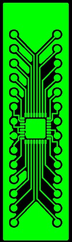
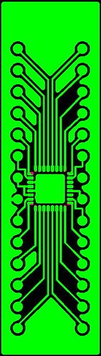
jandirks wrote:My first design lacked the center pad and my beta tester couldn't get his mlf32 programmed. Luckily, there was a via that was connected to ground under the mlf32 and he soldered a very thin wire through this via in a way that it made contact with the center pad on the mlf32. After adding that wire, he could program his mlf32.
Greetings Jan,

Okay, good to hear you are moving forwards. As for the ground
problem, I wonder if the other three ground pads were not making
good contact? I would expect the center pad to be internally
connected to the AVR's GND pins (3,5,21).

You can check this with a DMM on ohms, or send a question
to Atmel to confirm (the data sheet is really foggy...).
jandirks wrote: The only problem after this was that he only could burn the bootloader once. A second try wouldn't work. We are investigating now if this could have to do with fuses... suggestions welcome!
Two things come to mind. Both are known 'gotchas' with AVRs.
(1) The ADC function is shared with part of PortC, the rest of
PortC is connected to the digital supply. AVCC (Pin 18) must
be connected to Vcc externally for the full PortC to operate.
If the ADC is used the AVCC pin should be connected to VCC
with a low pass filter (to keep supply noise out of the ADC).
If by chance the AVCC pin was not connected (due to the
second touchdown on your fixture) the AVR may not work.

(2) The internal fuses select several functions and options.
If you are using ISP serial programing and internal RC Osc.
it's important that you don't accidently set the clock to Ext.
The AVR will freeze. It is possible to reverse the fuses (they
are called fuses but are really EEPROM bits). It is also
possible to drive an external clock into the AVR and reset
the fuses to int RC Osc.

Any AVR chip that programs once and not a second time
could be a victim of lost (external) clocks. There are also
security modes that are set with fuses to prevent the
code from being read out and also to prevent the AVR
from reprogramming. (i.e. You only get one chance).

I have 'burned out' a few AVRs with faulty ISP on prototypes,
but been able to reset the fuses with parallel programming
and external clock using the STK500 demo board.

Finally, when you are programming with ISP for the first
time make sure the ISP clock rate (not the AVR clock)
is very low. If the ISP clock get out of step it can result
in the AVR fuses changing to "one time only" programming.
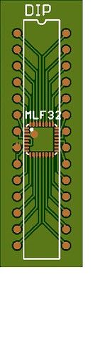
jandirks wrote:Could you please explain what you mean with 'building up' pads?
Sure. The PCB will have HAL (Hot Air Level) of the plating
over the copper traces and pads. These are masked by the
solder mask which has a thin but finite thickness. It is possible
that your physical contact from trace/pad to MLF/pad is lost
due to these weak or open electrical contacts.

To reduce this risk you can "build up' the pads by adding
solder to the MLF pads on your carrier PCB. That way there
are small bumps of solder above the solder mask. These
can contact the MLF pads on the AVR chip.

Because the solder is soft the tops of the bumps may be
damaged by the MLF, and you might have to reset them.

I'd think that solder paste would be a good start, and
possibly using a flux pen and reheating the solder with
hot air will get you back to nice even bumps.

Comments Welcome!
By jandirks
#37582
Peter,

Thanks again for your help and sorry for my late response!

bigglez wrote:
Two things come to mind. Both are known 'gotchas' with AVRs.
(1) The ADC function is shared with part of PortC, the rest of
PortC is connected to the digital supply. AVCC (Pin 18) must
be connected to Vcc externally for the full PortC to operate.
If the ADC is used the AVCC pin should be connected to VCC
with a low pass filter (to keep supply noise out of the ADC).
If by chance the AVCC pin was not connected (due to the
second touchdown on your fixture) the AVR may not work.

(2) The internal fuses select several functions and options.
If you are using ISP serial programing and internal RC Osc.
it's important that you don't accidently set the clock to Ext.
The AVR will freeze. It is possible to reverse the fuses (they
are called fuses but are really EEPROM bits). It is also
possible to drive an external clock into the AVR and reset
the fuses to int RC Osc.

Any AVR chip that programs once and not a second time
could be a victim of lost (external) clocks. There are also
security modes that are set with fuses to prevent the
code from being read out and also to prevent the AVR
from reprogramming. (i.e. You only get one chance).

I have 'burned out' a few AVRs with faulty ISP on prototypes,
but been able to reset the fuses with parallel programming
and external clock using the STK500 demo board.

Finally, when you are programming with ISP for the first
time make sure the ISP clock rate (not the AVR clock)
is very low. If the ISP clock get out of step it can result
in the AVR fuses changing to "one time only" programming.
I will keep this in mind when I start burning MLF32's. I never realized there so much to look at before starting with this!

Thanks again!