SparkFun Forums 

Where electronics enthusiasts find answers.

Questions relating to designing PCBs
By bryon
#35261
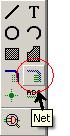
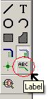
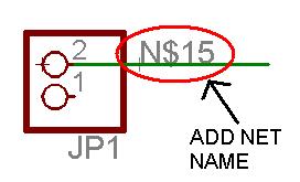
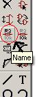
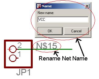
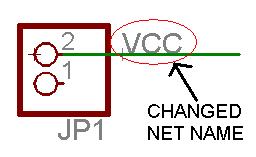
okay, I don't know the proper terminology but you know how on some schematics you see pins or connections labeled instead of a net wire between them? They are connected but just have labels to make the schem look neater. Yeah, those.

Anyone know how to do those in Eagle?

Thanks!
Bryon
By reklipz
#35263
I believe you just use the name tool, and it will place the name of the net out there.
By rpcelectronics
#35274
Using nets in Eagle is easy. Here are the steps:

Select NET tool:
Image

Add NET to a pin like a wire:
Image

Select LABEL tool:
Image

Add LABEL to the NET:
Image

Select NAME tool:
Image

Select LABEL and change name in pop up, click ok:
Image

Final NET with changed LABEL:
Image

Repeat these steps on any pin that you wish to connect and make sure you keep the net name the SAME. When you do that correctly, Eagle will pop up a window asking if you wish for these nets to be connected.

Good luck,
By Philba
#35292
good description.

Note that entering a pre-existing name will cause a connection to that net. very useful to make connections with out actually drawing them. I do that all the time to have clean schematics. Of course, then you definitely want labels so you can see what's what.
By bryon
#35316
This is great! Thanks for the help and the great tutorial!

Bryon
By Andrew02E
#35332
Search for 'symbol' in the 'Add' dialog and you'll find a bunch of nifty net-name tag thingers (found in the 'Frames' library). Gives your schematic that 'professional' look.