SparkFun Forums 

Where electronics enthusiasts find answers.

Have questions about a SparkFun product or board? This is the place to be.
User avatar
By bigglez
#31672
Greetings,

I'm interested in the Maxim LED display driver ICs (MAX7219/MAX7221), which were discussed here and here recently.

I've created an EVAL PCB in EAGLE if anyone is interested. BatchPCB is fabbing this one, I've just placed an order, so I expect to have it back in three weeks.

My first thoughts were to create a break-out board with the IC, some headers for comms and power, and a matrix of LEDs. I've packed the 1206 size LEDs into a square matrix (8x8), which will illiminate the tedious wiring and allow for character or graphics mapping experiments.

Throwing the KISS principle to one side, I've extended the PCB design to also include an AVR, RS-232 port, some EEPROM and an RTC (with battery back up). Apart from the MAXIM created PC parallel port I've included a single push switch and a rotary encoder for manual data entry. Enough hardware to do a few projects!

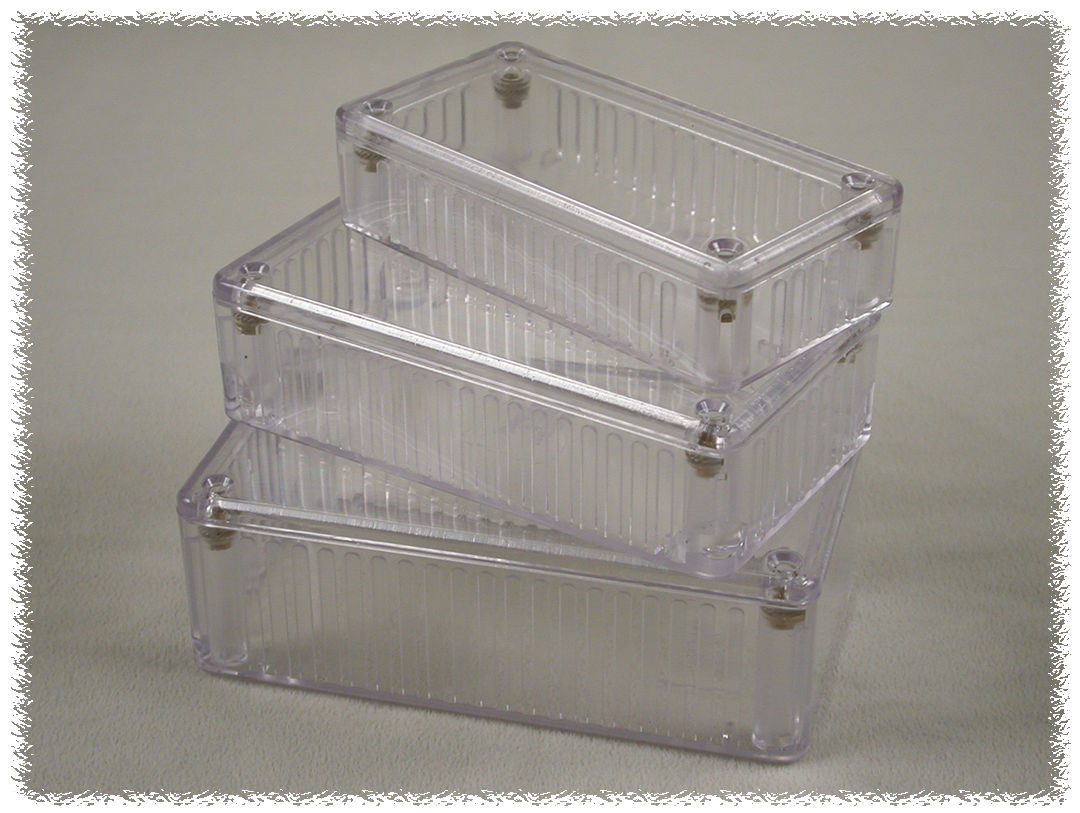
Also, I've had a cute clear plastic enclosure sitting on my work bench for a while, just waiting for a project, so this PCB has been notched to fit.

Anyone else working with the MAX7219/MAX7221? Any suggestions for this EVAL PCB?

Comments Welcome!
User avatar
By bigglez
#32398
bigglez wrote:BatchPCB is fabbing this one, I've just placed an order, so I expect to have it back in three weeks.
Well, someone at BatchPCB dropped the ball. No PCB. Their best guess in two weeks from now. Bummer.
By Pyrofer
#32408
Thanks for the heads up on that IC!

I didnt know about it, ive just ordered some to try out (DIP). You do know you can buy pre-build 8x8 led matrix displays right? Saves a LOT of soldering too. Some are even multicolour.
User avatar
By bigglez
#32426
Pyrofer wrote:You do know you can buy pre-build 8x8 led matrix displays right? Saves a LOT of soldering too. Some are even multicolour.
Greetings Pyrofer,

Do you have a link to those commercial eval boards?

My board has several features:

(1) Support 64 1206 SMD LEDs in a square grid
(2) MAX7219/MAX7221 SIOC
(3) Interface to PC parallel port (for MAXIM VB demo software)
(4) AVR Mega 8
(5) DS1307 RTC I2C bus w/battery back up and 1pps LED
(6) EEPROM (16kB for fonts and annimation sequences) on I2C bus
(7) RS232 comms port
(8) Rotary encoder and switch for user interface
(9) Fits in Hammond 1521C plastic enclosure (Red, Clear, Ice Blue)

I expect to get several different projects out of the hardware, once I have a grip on the MAX IC protocol.

Comments Welcome!
User avatar
By bigglez
#32878
bigglez wrote:
bigglez wrote:BatchPCB is fabbing this one, I've just placed an order, so I expect to have it back in three weeks.
Greetings,

The PCB has been assembled (no circuit or layout errors - a few silk-screen gotchas...). I fiddled with the array of 64 LEDs and got them all lined up (without burning any out while "soldering" with a heat gun).

I have it running from a PC using the MAXIM VB software. Looks like an error in the MAXIM software as the Shutdown bit is inverted - so the display is blank when it should light up, and vice versa.

Otherwise, it very Kewl and very bright.

Also, the DP bit is the MSB, I have the layout with the DP as the LSB, so the patterns on the LEDs don't match the bit banging in the utility software. (Not a show stopper, I just have to swap the MSB (bit7) and bit6 in software on the AVR.

The RTC (on my PCB) is alive, the heartbeat LED is blinking at 1pps.

So, I can cut the umbilical cord from the PC and use only the AVR (on my PCB) for the next steps. I will try to duplicate the MAXIM software control words and LED map in the AVR. Adding animation should be easy, too.

PIX to follow - I'm now late for dinner.

Comments Welcome!
User avatar
By bigglez
#32900
bigglez wrote:PIX to follow - I'm now late for dinner.
Image
Image
Image
Image
Image

Comments Welcome!
User avatar
By bigglez
#32996
ohararp wrote:Peter do you mind sharing the schematics for your design? I would really like to do a circular matrix for an up coming project.
Greetings ohararp,

Sure! I hope you (or others) can get some use or inspiration from my work.

Here's the files used by BatchPCB for the X1 board (plus the BOM as a word doc and a board outline image as jpg). Here's simple BASCOM Basic codeto wake the board up and run a demo annimation).

Errata:
I changed the EEPROM type. When using a 128kb IC )instead of the 1kb I have on the schematic) the EEPROM is forced to "read only" (Write Protect pin7 to Vcc instead of gnd). For large EEPROMs lift pin7 and link to ground so that it can be written by the AVR.

The silk-screen for the EEPROM didn't print. Use the EAGLE files to find pin1 (its rotated compared to the RTC next to it).

R8 (optional pull up from the encoder pin B) is too close to the body of the encoder. (Hint: move it slightly, mount the encoder on the back of the board - my original plan, or, leave it off and set the AVR port B1 to internal pull-up).

I have a spare PCB if you'd like to build it - PM me to discuss.

Comments Welcome!
User avatar
By bigglez
#32999
ohararp wrote:Peter, sorry...any chance you can make the schematic a .jpeg for easy viewing without the layout software?
Here is sheet1
Here is sheet2


(BTW, you can download the free eval EAGLE and get a lot more detail from the schemaitc compared with a 'frozen' jpeg...)

Comments Welcome!
By Lucien
#33284
Peter, that looks very cool. I was thinking it might be even neater to use an array of 0603 leds in a tight grid, but looks like someone's already pulled that off. Though not with the MAX7219/MAX7221.

Might still be fun to look into though, daisy-chaining 3 together to make a 24x8 display.

Also, according to the pin description in the datasheet, DIG 0–DIG 7 go to V+ and SEG A–SEG G go to GND when turned off. I wonder if you could put a second reversed LED in there to get a different colour when a pixel is off.
User avatar
By bigglez
#33300
Lucien wrote: Peter, that looks very cool. I was thinking it might be even neater to use an array of 0603 leds in a tight grid, but looks like someone's already pulled that off. Though not with the MAX7219/MAX7221.
Greetings Lucien,

Nice link, thanks! I've seen name badges with LED matrix displays, but this project took it a step further (touch switches and a future RF link. I placed the 1206 LEDs to get a square PIXEL matrix. I'm gaining confidence to step down from 1206 to, say, 0805 parts in the future.

The MAX part illiminates the resistors needed with pure logic LED drivers, and also offers dimming (of the entire display, not by row, by column, or by PIXEL).
Lucien wrote: Might still be fun to look into though, daisy-chaining 3 together to make a 24x8 display.
I've built two (red and green) and have begged MAX for a few more samples. I was going to use yellow LED next, but obviously blue would be the logical choice.
Lucien wrote: Also, according to the pin description in the datasheet, DIG 0–DIG 7 go to V+ and SEG A–SEG G go to GND when turned off. I wonder if you could put a second reversed LED in there to get a different colour when a pixel is off.
Well, that's a thought! I saw the comments in the data sheet, but it didn't explain if the 'off state' was a hard switch to the rails or if there is a current limiter in play. The reverse LED scheme might require a resistor per LED (ouch!) or at least one per Row or Column.

It could produce two colour effects but I don't think you can blank the display.

BTW, the 1206 LEDs I'm using can be seen from the rear (through the PCB). Interesting diffused arty look.

Comments Welcome!
User avatar
By bigglez
#33301
ohararp wrote:Peter thanks for the schematic. I was able to submit a quick design with a small panel I just had done up. You can check out a quick video at www.ohararp.com/blog . I used the max7219 and tied it to my easypic4 dev board.
Greetings Ohara,

Enjoyed your blog! The MAX part opens a lot of possibilities for "blinky LEDs". Now that I have one working I want to try it out for Alpha numeric fonts. I should probably have done a 7x9 instead of 8x8 grid...

Comments Welcome!
By Lucien
#33328
bigglez wrote:
Lucien wrote: Also, according to the pin description in the datasheet, DIG 0–DIG 7 go to V+ and SEG A–SEG G go to GND when turned off. I wonder if you could put a second reversed LED in there to get a different colour when a pixel is off.
Well, that's a thought! I saw the comments in the data sheet, but it didn't explain if the 'off state' was a hard switch to the rails or if there is a current limiter in play. The reverse LED scheme might require a resistor per LED (ouch!) or at least one per Row or Column.

It could produce two colour effects but I don't think you can blank the display.

BTW, the 1206 LEDs I'm using can be seen from the rear (through the PCB). Interesting diffused arty look.

Comments Welcome!
Yep, the problem would be no current limiting when a pixel was "off" and that there'd be no way to have it unlit.

On the subject of "viewable from the rear", I've seen some SMD LEDs made for reverse mounting, where the LED is meant to shine through a hole in the PCB between the pads. I think they were made by Avago.
bigglez wrote:Enjoyed your blog! The MAX part opens a lot of possibilities for "blinky LEDs". Now that I have one working I want to try it out for Alpha numeric fonts. I should probably have done a 7x9 instead of 8x8 grid...
Would a 7x9 be doable with the 7219/7221? I wouldn't have thought you'd be able to swap the function of a line around on these chips.

Cheers!