
- Thu May 20, 2021 7:09 pm
#226082
Hi there,
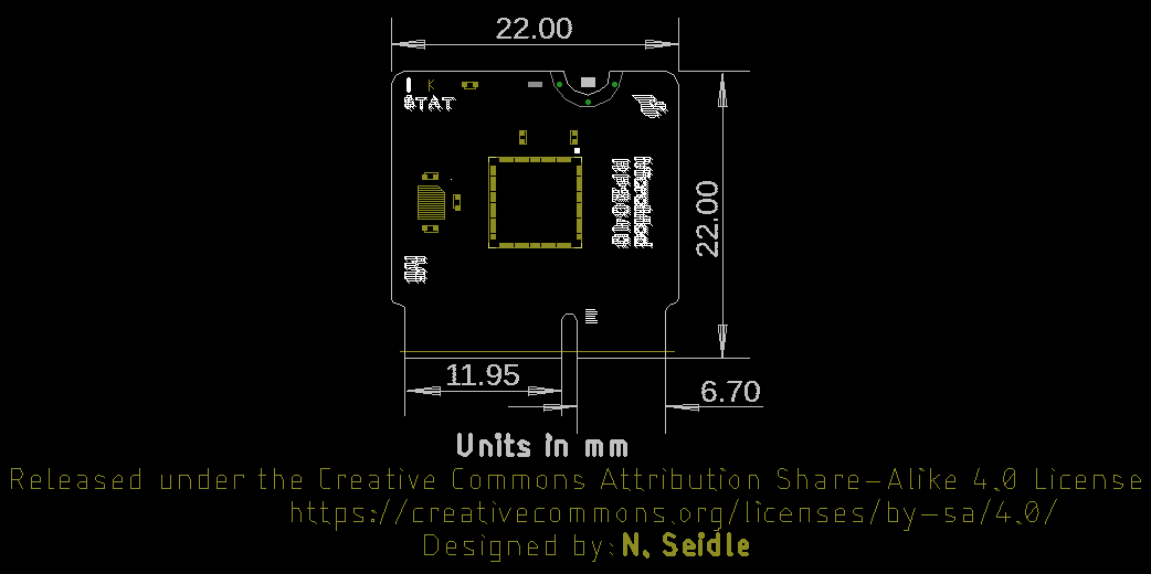
I'm working on a carrier board for the RP2040 MicroMod (https://learn.sparkfun.com/tutorials/de ... 1599036432), and I swear I'm going crazy. Are there published mechanical drawings of this board anywhere other than this picture?:(https://cdn.sparkfun.com/assets/learn_t ... nsions.png)
Specifically, what I'd like to glean:
1. Precisely where to center my M2.5 standoff
2. How much of the board will be extending out of the M.2 connector when fully inserted
3. How wide the notch is
4. Radii on the various edges
4a. How much width is lost on the M.2 card edge due to the radii
Any help is appreciated on this. Hopefully someone has produced a proper mechanical draft, but at this point I'll even take someone with a board, some calipers, and a steady hand!
Thank you!


