Oops, when I mentioned that "it's a bit difficult to measure", I was actually replying to Codlink's reply, didn't see your post sneak in there.
I ran a battery of tests tonight. I did measure the voltage at the battery as the motor spun up. They started at about 24.05 volts, and never dropped below 24.00. Thinking about it a bit, I should have used the "minimum" setting on the meter, in case the voltage was dropping very quickly, then equalizing. I'll try that next time. Again, I'm pretty confidant that the batteries can handle the ~10 amp draw all day long without sweating.
I tried the suggested experiment. I started with the thin jumpers on, let the motor spin up, then used a much beefier jumper to connect the two. There was a slight change in sound coming from the motor, but nothing significant. I tried doing the full spin up/down cycle with the beefier cables, and they too sound much better than directly connecting the motor to the controller. The thin set of cables is probably 20 gauge or smaller, the beefier cables are 12 gauge. While there's a slight difference when testing with either set, they both offer much better behavior than the direct connection method.
I busted out the hand-me-down oscilloscope, and measured the output at both the motor and each leg of the hbridge. I've been waiting years to put this thing to use.
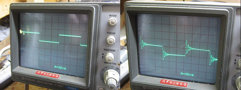
The output at the motor looked like this. The left image is without the motor attached, the right is with the motor attached to the controller.
The measurement at the legs of the FETs were more interesting. The top two images show what the switching waveform of the leg looks like. The left picture is again without the motor, the second picture is with the motor on. The motor is definitely throwing some interference of some sort in there, but it's not too significant.
The bottom two pictures are the waveform when the leg should have been fully on or off (It looks like I took the picture on different legs, but you get the idea). The left image is with the motor attached directly to the controller. It's a very noisy signal, it should be a flat line. The right image is with the thin cables attached. It's much cleaner.

I also tried several different PWM-ing frequencies. I tried much lower (1 khz), which kept the board cool, but was very loud, up to 16khz, which was less noisy, but heated up the FETs seriously, and still didn't sound "right". I typically run at 8 khz, which is what the previous skateboard used with no issue with the same motor (but different controller).
I'll keep troubleshooting the board, it does seem like something is fundamentally wrong with it.
Pete