SparkFun Forums 

Where electronics enthusiasts find answers.

All things pertaining to wireless and RF links
By donaldhwong
#178524
I am following this instruction.. http://letsmakerobots.com/node/37243

Both RSSI LED on the two XBEE S2 USB Explorers are lit. Arduino RX is receiving about 20 bytes. But the value from pulseIn() from three of the PWM Arduino pins are still ZERO, connected to pin 6 (RSSI) of Xbee.

How can I fix it? Please advise.

Thank you,
Donald
By Valen
#178572
First start would be to read the Xbee manual from Digi and learn the functions of the device. Receiving 20 bytes from the Xbee into the Arduino suggests those may be API packets (which could contain RSSI values). That manual also explains how the RSSI output can be enabled/disabled. The RSSI led/pin can also be set as a generic PWM output. Without knowing how your Xbee settings are it's just a guessing game what might be the cause. Please use XCTU to save all configuration settings to a text file and upload it to here.

PulseIn() doesn't have to be used on the PWM pins. Those are designated to be hardware PWM outputs. PulseIn can use any digital pin (if it is not needed for something else). Again, without knowing what Arduino code you have runnig it is impossible to tell what is going wrong.

P.S. Which Arduino board are you using? Is it a 5 volt based board?
By donaldhwong
#178650
Hi Valen,

Thank you so much for such detailed suggestions. YES, I am a complete newbie. As per your advice, I have studied the Xbee Manual. It is more complicated than my needs. But I did learn how capable it is.

I am using a 3.3v Moteino MEGA.

As per your instruction, I have attached both simple basic configuration files as well as the Arduino sketch herewith.

As I mentioned, though the RSSI LED is lit, but the pulseIn() still reads ZERO.

Thank you for your continual support. Have a nice day.

Donald
You do not have the required permissions to view the files attached to this post.
By Valen
#178673
Remember that RSSI pin 6 of the 2mm pitch Xbee connector isn't the same as the 6th hole on the .1" pitch connector of the Xbee Explorer USB. Infact, RSSI is the 7th hole on the board if you start counting 1 from the RSSI led. Sparkfun is a bit confusing with their chosen pin count scheme.

Since you are a beginner I have to emphasize that aside from connecting the RSSI pin to the Moteino you also need to connect the ground GND pin to it. Only 1 wire won't do.

While you are at it. Please make a photo of the setup of your Xbee Explorer USB, MoteinoMega and how the wires between them run. It is unclear how the serial pins are connected. The code expects 2 serial devices. "Serial" being the connection to the PC, and Serial1 being the connection to the XBee. But you probably have the Xbee ontop of the Explorer board, which is then connected directly to you pc. .... IF I am correct in my understanding sofar. So I'm not going to have a look at those Xbee settings yet. I want to make sure the electronics are wired up good first.

Do you get any other (readable) text sent across the serial port to the pc? If not, then it is not hooked up as intended.

I took a look at the Moteino website here:

http://lowpowerlab.com/moteino/#designfiles

But I don't understand to which UART port (Serial, or Serial1) those RX and TX on the (short-)side connector are connected to on the chip. So, if it is TX0/RX0, or TX1/RX1. I may not have searched well enough, but I couldn't find a schematic of the MoteinoMega in pdf.
By donaldhwong
#178675
Hi Valen,

Thank you so much for your quick and detailed reply. Yes, I am a newbie to Arduino & Xbee, but 30 years ago I was educated as a digital EE. Just haven't touch digital electronics for 30 years. LOL.

Uploaded please find Moteino MEGA, Serial0 is connected to PC by default. So the Xbee DOUT is connected to Pin 10 of MEGA, and Xbee DIN connects to Pin 11 of MEGA. While RSSI Pin 7/6 is connected to PIN 12 of MEGA.

Yes, I am getting about 20 bytes of data from Xbee.

If you must see a photo of the wiring, I will upload it.

Thank you again.
Donald
You do not have the required permissions to view the files attached to this post.
By Valen
#178679
I've seen that pinout diagram, but it didn't explain where that yellow and orange TX/RX goes to. But I guess it is logical that it is for "Serial", the default UART.

Any chance that you can record the serial data it with the serial monitor in XCTU? It has the option of showing the bytes in hexadecimal notation. Knowing that it is easier to analyse what the code is processing. It starts the pulse duration measurement, after a specific sequence of bytes have passed. If that doesn't happen as expected then the led has no chance of changing.

I found a Youtube video of the guy that wrote that sketch. His Din to Rx/Dout to Tx connections don't make sense.
https://www.youtube.com/watch?v=1Bz95LL5tZ4

He tilts his Chip antenna Xbee, which is not very omni directional outside of the chip-antenna plane. (years ago I read a Digi/Maxstream document with their antenna receptivity paterns comparison) This is more likely the reason that the RSSI changes, rather than the range change which seems only a couple of inches. So be carefull how you move the Xbee yourself.
But like him you should also be able to receive the measured pulselength values over the serial connection to your PC. Are you not getting that?

P.s The code only lights led if it detects a Low-pulse of certain minimum duration. It isn't proportional to the RSSI duration.
By donaldhwong
#178697
Hi Valen,

Thank you for your quick response. I am getting the following HEX from the RX input to the Moteino MEGA..
01292013A2040C4586696B721008
0
01292013A2040C4586696B721008
0
01292013A2040C4586696B721008
0
The ZERO is the RSSI pin readout.

If I can grab the RSSI, I can Serial.print it. I will make sure that I move the Xbee properly.

Thank you again,
Donald
By stevech
#178698
XBees report RSSI as a one byte value sent within a Digi Xbee binary API data frame. The RSSI byte can be interpreted as -dBm.
By donaldhwong
#178699
Hi Steve, Thank you. It's true for Series ONE. But Series 2 no longer embed RSSI info in their API frame.
By Valen
#178713
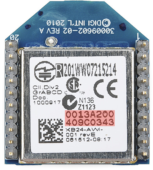
Can you write the serial numbers (SH and SL register) of both Xbees? There is also a sticker on the back with it.
Image

I recognise the start of a serial number (13A2) in the hex string, but the XCTU API frame interpreter cannot make heads or tails out of this. Probably because the serial monitor that is used doesn't insert leading zeros where necessary, but there is no 0x7E frame header to be seen either. If you ask me it does not seem to reflect the processing of that sketch. You can prove it by inserting the command Serial.print("RSSI"); . It would have to show up in the string.
...
if(Serial1.read() == 0x7E) { // Reads the start byte
for(int i = 1; i < 19; i++) {
byte discardByte = Serial1.read();


rssiDur = pulseIn(digitalPin, LOW, 200); // get's the RSSI Value
Serial.print("RSSI:");
Serial.println(rssiDur); //for debbuging and first setup.
...
Please do make a proper schematic of how this is wired up, or make photographs. Pictures say more than words.
By donaldhwong
#178716
HI Valen,

Thank you for your continuous support. I inserted the RSSI label and obtain the following:
01292013A2040C45866C42221008
RSSI:0
01292013A2040C45866C42221008
RSSI:0
01292013A2040C45866C42221008
RSSI:0
01292013A2040C45866C42221008
RSSI:0
The Router is 13A200-40C45866
The Coordinator is 13A200-40C4583C

XCTU Gave me the following:
IO Data Sample RX Indicator (API 1)

7E 00 12 92 00 13 A2 00 40 C4 58 66 C4 22 02 01 00 00 08 02 0F F4

- Start delimiter: 7E
- Length: 00 12 (18)
- Frame type: 92 (IO Data Sample RX Indicator)
- 64-bit source address: 00 13 A2 00 40 C4 58 66
- 16-bit source address: C4 22
- Receive options: 02
- Number of samples: 01
- Digital channel mask: 00 00
- Analog channel mask: 08
- Analog sample: 02 0F
- Checksum: F4
Se hookup photo also.

Thank you looking after me. Really appreciated.
You do not have the required permissions to view the files attached to this post.
By stevech
#178732
donaldhwong wrote:Hi Steve, Thank you. It's true for Series ONE. But Series 2 no longer embed RSSI info in their API frame.

Besides the miserable ZigBee protocol stack, another reason to use S1. If you must mesh, use DigiMesh on S1.

There is a decent free Arduino library for XBee S1 and S2. That's Arduino as in Atmel AVR 328 and the like MCUs.
By donaldhwong
#178733
Hi Steve,

Thank you for your input. I purchased S2, because the sample URL uses S2. This is my first venture into Xbee. You think I should return the S2 and change it with S1?

Does S1 also have a RSSI output pin? I looked and can not find it.

I have downloaded the Xbee library, but no need to use it yet. Can you give me one, regarding RSSI?
By Valen
#178738
This is starting to make sense now. That packet is a report of an analog measurement on the router xbee. Was this the one to which the moteino was hooked up? This is lacking in my understanding. Was it comming out of the coordinator, or out of the router? If the latter then there wasn't any rf traffic to cause the rssi timer to update. If the former then there must have been rf traffic. How far are the xbee modules apart? I'll have another look at the config files that you uploaded later. I'm busy now.