- Wed Mar 21, 2012 10:39 am
#141567
I am starting my first PCB design that will be a little complicated for a first design, so I've read through these forums and made some notes and thought I would share it. Maybe noobs like my self could find this useful.
EagleCAD NOTES for xxx
* Decoupling capacitors needed as clost to 1284p as possible where ever Vcc & Grn pinnned out
* Smaller = quicker responce
* Pick the largest capacitance in the smallest package
* 1 10uF tantalum cap per major IC microcontroller
* 0.1uF and a 10nF cap at every power pin on every IC
* The 10nF caps need to be small, preferable 0402 or at most 0603 sized to avoid the lead inductance
from the package nullifying the effect of the capacitor.
* Traces should not connect at acute angles; "can form acid traps" (No less than 45 degrees)
* Route critical nets like supplies first, with wide tracks
* No 90 degree angles for professionalism
* "Mitre" 90 degree bends in tracks
* Traces should run straight into pads to avoid acid traps
*OK'ed examples:
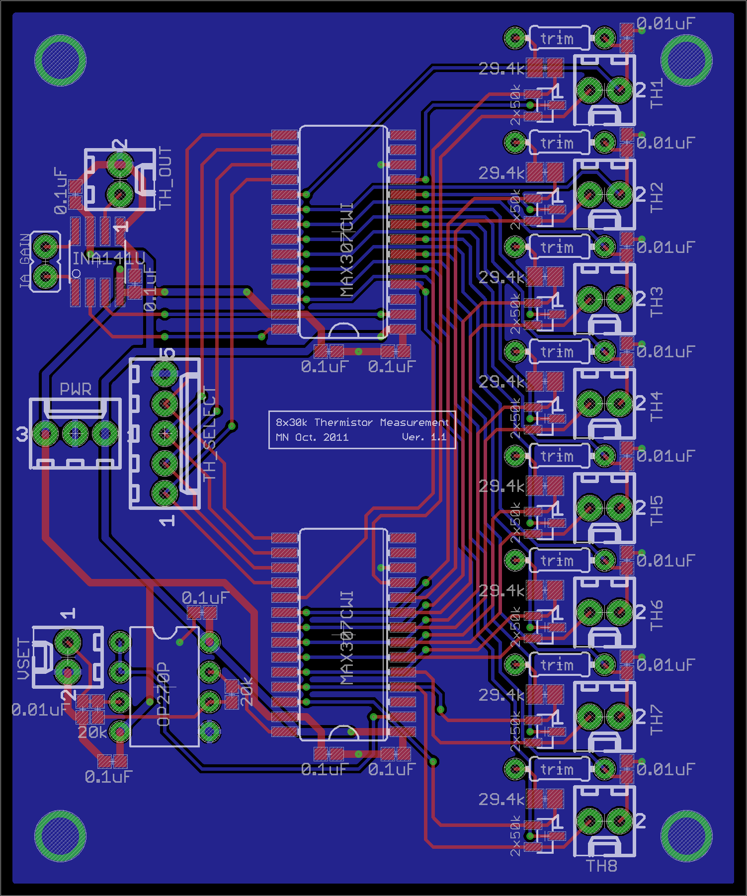
* http://jila1.nickersonm.com/thermmeas_all_1.1.png
* http://desmond.imageshack.us/Himg705/sc ... res=medium
* Wide Vcc line
* Use more direct and wider (lower impedance) Vcc trace
* On a standard PCB allowing 10°C temperature rise, an external 16mil trace will carry ~1.2A
* Vcc trace should go to the cap first and then to the chip through a short wide trace
* Trace calculator: http://circuitcalculator.com/wordpress/ ... alculator/
* Ground
* Make to bottom copper pour ground and connect all to this pour.
* Diodes
* Normal diode for the batteries, which will match all the supplies when tied together at just below 5V
* Resistors
* Atmel recommends a 4k7 - 10k pullup resistor on ~RESET
* Crystals
* The caps for the crystal need to be right next to the crystal
* May need to tie the unused inputs either high or low
* The Arduino and other micros have multiple ground pins; I would tie them all to ground;
*Auto routing is not a good idea:
* Forget autorouting - manual route it, unless you have an outorouter that costs >10k
*Great Tutorial someone posted: http://www.alternatezone.com/electronic ... alRevA.pdf
*Dont know how true this is but: "With BatchPCB, they usually send twice as many boards as you order."
*On average:
Traces: 16mil (32mil for power)
Spacing:10mil
Minimum drill: 20mil (vias)
Primary grid: 10mil
Alt grid: 5mil
If it's a more complex, tight board you might want to use something like this
Traces: 10mil
Spacing: 10mil
Minimum drill: 15mil (IF you can)
Primary grid: 5mil
Alt: 2.5mil
EagleCAD NOTES for xxx
* Decoupling capacitors needed as clost to 1284p as possible where ever Vcc & Grn pinnned out
* Smaller = quicker responce
* Pick the largest capacitance in the smallest package
* 1 10uF tantalum cap per major IC microcontroller
* 0.1uF and a 10nF cap at every power pin on every IC
* The 10nF caps need to be small, preferable 0402 or at most 0603 sized to avoid the lead inductance
from the package nullifying the effect of the capacitor.
* Traces should not connect at acute angles; "can form acid traps" (No less than 45 degrees)
* Route critical nets like supplies first, with wide tracks
* No 90 degree angles for professionalism
* "Mitre" 90 degree bends in tracks
* Traces should run straight into pads to avoid acid traps
*OK'ed examples:
* http://jila1.nickersonm.com/thermmeas_all_1.1.png
* http://desmond.imageshack.us/Himg705/sc ... res=medium
* Wide Vcc line
* Use more direct and wider (lower impedance) Vcc trace
* On a standard PCB allowing 10°C temperature rise, an external 16mil trace will carry ~1.2A
* Vcc trace should go to the cap first and then to the chip through a short wide trace
* Trace calculator: http://circuitcalculator.com/wordpress/ ... alculator/
* Ground
* Make to bottom copper pour ground and connect all to this pour.
* Diodes
* Normal diode for the batteries, which will match all the supplies when tied together at just below 5V
* Resistors
* Atmel recommends a 4k7 - 10k pullup resistor on ~RESET
* Crystals
* The caps for the crystal need to be right next to the crystal
* May need to tie the unused inputs either high or low
* The Arduino and other micros have multiple ground pins; I would tie them all to ground;
*Auto routing is not a good idea:
* Forget autorouting - manual route it, unless you have an outorouter that costs >10k
*Great Tutorial someone posted: http://www.alternatezone.com/electronic ... alRevA.pdf
*Dont know how true this is but: "With BatchPCB, they usually send twice as many boards as you order."
*On average:
Traces: 16mil (32mil for power)
Spacing:10mil
Minimum drill: 20mil (vias)
Primary grid: 10mil
Alt grid: 5mil
If it's a more complex, tight board you might want to use something like this
Traces: 10mil
Spacing: 10mil
Minimum drill: 15mil (IF you can)
Primary grid: 5mil
Alt: 2.5mil