st2000 wrote:
As you might have figured out (or at least I assume) after upgrading you iPod(s) you no longer get any video out of your break-out board (or do you???).
What I am thinking you might be able to do is buy an Apple video cable, extract the chip and install it into your break-out board. Or, at the very least, integrate an Apple video cable into your design. I am assuming Apple uses the serial I/O of an iPod 30 pin interface to communicate with a chip in the cable. There's not much you can do to beat the system if it's what I think it is. That is, unless Apple implemented it badly (i.e. used the same starting challenge sequence after, say, a iPod reset).
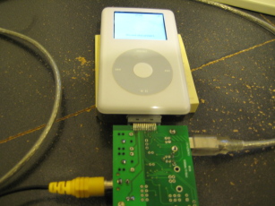
Actually I hadn't explicitly tested video out with anything other than my (4th gen Classic?) iPod Photo.
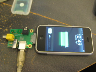
I just tested my iPhone with composite video and your right, it doesn't do anything. Thanks for the heads up.

To be honest, I'm not thrilled about the idea of cannibalizing Apple video cables if I can help it. Even cheap South-Asia versions of the adapter are at least $10 each, and thats an extra ten bucks I'd need to add to the price of anything I produce. Reverse engineering an official video cable may be in my future, although if its anything more complex than a resistor value on the accessory select line or a static challenge/response on the serial line I'll probably be wandering into DMCA territory.
st2000 wrote:
Old iPods charged from the 12V fire wire line. New iPods charge from the 5V USB wire line. Why not add a buck-converter when attaching, say, an iPhone to a computer's fire wire line and a boost-converter when attaching a really old iPod to a computer's USB port. There are plenty of single chip solutions that only need a half dozen external components. You could lay them out on you PCB and leave it up to the end user if he/she wants to populate them.
As a matter of fact I had looked into various charging solutions when doing the initial design, but the hassle of layout, limited board space, and fear of destroying an iPod (or attached computer) with bad circuit design is why there isn't an external power jack or similar on the board already. I figured I'd break out the connector pins and let the user use a
MintyBoost or similar if they needed more power.
Here is my logic:
When going from USB->Firewire I'd be worried about current supply. To stay within the bounds of the USB spec I would need to limit current draw to 100mA (or 500Ma if the board 'asked for permission' over USB, but that is a bit complex). Correct me if I'm wrong but the ratio between the voltage and current would be maintained and thus if the board converted the USB power to 12V the current would drop significantly. Would a Firewire iPod charge at less than 100mA? Would it charge in a reasonable amount of time?
Regarding Firewire->USB charging: since Firewire was intended to operate full size hard drive I assume it provides more than 100mA, so in theory I could just throw a linear regulator and a couple resistors on the board and call it good. Problem is I'd still need to add some extra logic to detect if the device doesn't use Firewire (not sure how to do this), cut off Firewire data lines (I have reason to believe they've been repurposed in newer devices and driving signals on them could result in undefined behavior in the device), pull the USB signal lines to appropriate levels (so it will actually see the board as a charger), and to disconnect the charge circuitry when something is plugged in the USB socket. If I screw that logic up I could potentially damage somebodies computer or expensive Apple device, and I
really don't want to do that. As I said above, I just broke out the pins and decided to let the user pick their power supply.