SparkFun Forums 

Where electronics enthusiasts find answers.

Discussions on how to get your MSP JTAG programmer up and running.
By stube40
#131934
I'm trying to debug a weird issue by where my firmware resets itself whilst running on a MSP430F2274 - that is, it returns to the first line of assembler code labelled 'cstart_begin' in the disassembly.

If I put a breakpoint on the line of assembler code previous to cstart_begin, it never fires - hence it must be jumping to here.

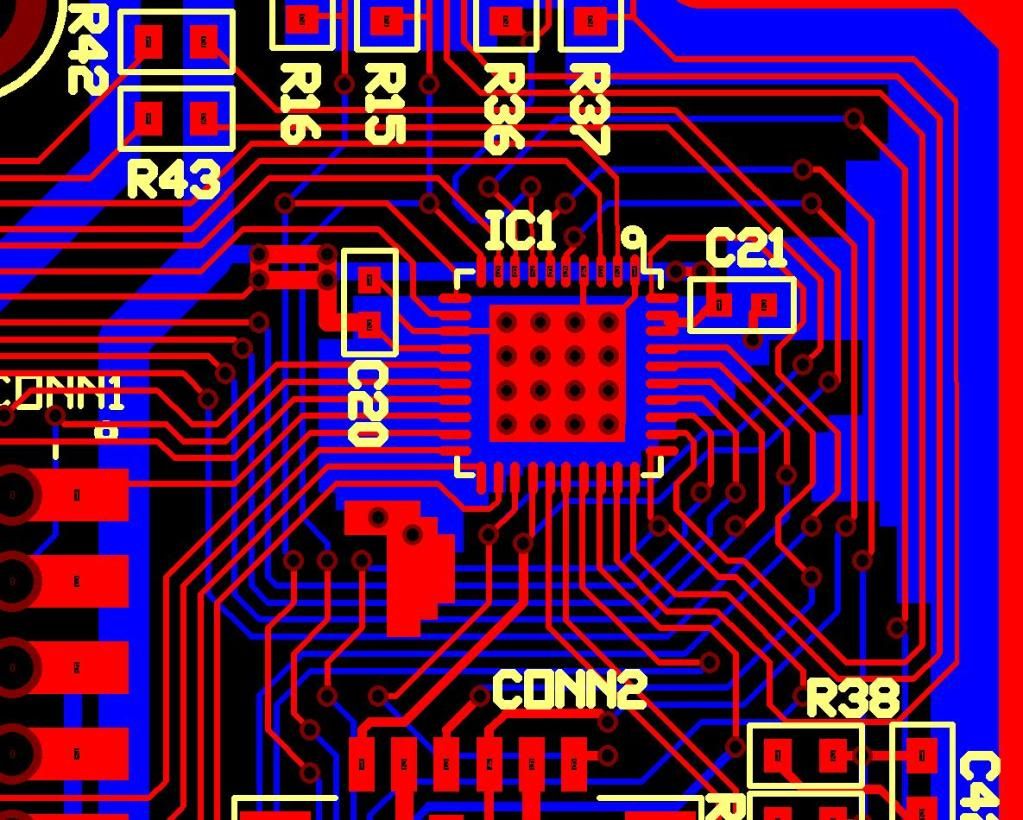
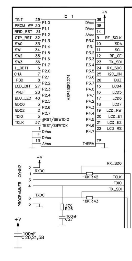
To shed a bit more light on this, I have my own custom hardware PCB with a few chips hanging off the I2C bus. These I2C chips have a power rail which can be switched on/off via a MOSFET controlled by a single bit on PORT3 of the CPU. It's when I'm switching the I2C rail ON that the resets happen. Not every single time, just sometimes.

It's weird and I suspected a power surge issue, but I've tried various different PSUs and hence I'm pretty confident there is enough power. Although, I haven't yet scoped it to see if there is a spike.

However, the firmware behaviour seems weird. Why does it jump to cstart_begin? What makes it jump? Can anyone shed more light on this?

Thanks,
Stuart.
By pabigot
#131947
Might be a voltage sag resulting in a brown-out reset, or some other fault condition resulting in a power-up clear. It would be worth caching the value of the SVSFG flag on the SVSCTL register, and the other PORIFG/RSTIFG/OFIFG/etc flags, as the first thing you do on startup, and examining them for clues. Chapter 2 of SLAU144H, the 2xx family user's guide describes some of the situations where the chip will reset itself.
By fll-freak
#131957
ARGHHHH!

I have two projects with the same #$#@@# problem. One is an MSP that drives a car horn (5 plus amps and nasty spikes) via an opto-isolator controlling a FET, controlling a relay driving the horn on its very own power supply. Not even ground is common. And yet the dang MPS430 resets.

The second project is a lightning detector that resets when a very strong pulse (5+ volts) comes in the antenna and into the front end.

First you must make sure you have all the proper bypass caps on the chip as close as possible to the power pins.

Second you must not allow any pin to be uncommitted. There is an app note at TI to tell you the best ways to commit a non-used pin. Either set the pin as an output, or set as an input with proper pull-up down. You will need to find that note and read it carefully. If left uncommitted, EMI can get into the chip via those pins.

Third, you need a good ground plane. My problems got better when I used a "doughnut per hole with ground plane" prototype board and soldered the project rather than breadboarding it.

Fourth, test without the debugger attached. One project I had would reboot because the USB cable for the programming pod was picking up noise and injecting it into the circuit.

But those hints still did not solve my car horn problem. That one has me pulling my hair out. Fully isolated, with 3 foot separation. No noticeable ground bounce or power rail glitches on the MSP as it gets it power from a different source. Enough caps or different sizes on the MSP for it run run for 5 minutes after power removal! Copper foil wrapped around the board. I suspect the car horn is generating tachyon emissions that are interfering with the internal time-space continuum, but that is just my current theory.

As for the issue with not executing the code before cstart. It may be that cstart is called from someplace else rather than being a chunk of code inline with that is before it. I would have to look at the implementation to see. Can you put breakpoint on the line before and have it stop there when you do a restart?
#131993
@flll_freak: Do you have any long wires? They make great antennas for EMI. You have probably heard this before but keep wires as short as possible to keep from picking up noise. If you cannot shorten them, try ferrite beads and RC filters on the lines going to the micro. You might even need to use shielded wire or coax. Also, are you sure it is a reset? Could it be an unhandled interrupt?

Hope this helps,

gm
By stube40
#132040
@flll_freak - I put a breakpoint on the line before cstart and it never fires. I have two decoupling caps, C20 and C21, both 100nF and right next to the chip as you can see from the PCB and schematic below. I will test you theory to go without the USB debugger attached and report back.

@pabigot - good advice to cache those registers. Will try that and report back.

Image
Image
#132051
I don't see where your reset line is being pulled high. It appears to be floating in your schematic. I believe that the 47K should go between your +V rail and the TDIO line and the cap should go between the TDIO line and ground.
By stube40
#132055
gm wrote:I don't see where your reset line is being pulled high. It appears to be floating in your schematic. I believe that the 47K should go between your +V rail and the TDIO line and the cap should go between the TDIO line and ground.
Yes, you are absolutely right. I modded the board to change to a 47k pull up, but it didn't make any difference to the reset issues I'm having at present.
By stube40
#132057
I put a scope on Vcc and found that it is dropping to 2.5V when I switch the I2C rail on (ie when the reset problem happens). I haven't found the part in the data sheet which tells you how low Vcc can go, but I'm thinking it must be at least 2.2V. Hence, could this be a brown-out issue?

Also, I declared traps for all unhandled interrupt vectors in case it was something to do with this, but I had issues compiling the reset vector. When I compiled the following in IAR I got the linker error:

#pragma vector = RESET_VECTOR
__interrupt void RESET_ISR(void)
{
while(1);
}

Error[e16]: Segment RESET (size: 0x2 align: 0x1) is too long for segment definition. At least 0x2 more bytes needed. The problem occurred while processing the segment placement command "-Z(CODE)RESET=FFFE-FFFF", where at the moment of placement the available memory ranges were "-none-"
Reserved ranges relevant to this placement:
ffe0-ffff INTVEC

I don't get it - it needs two bytes and it's got them, so why can't it compile?
By fll-freak
#132069
If memory serves me, the reset vector is where the processor starts. Your compiler will add code here to eventually get to cstart.

With my resets, the voltage never went into the brownout area. I could gradually lower the voltage and nothing would happen. But a sudden drop in voltage, and poof, the bugger would reset and not hit the brownout vector.
#132076
Are you powering the I2C rail from an I/O pin? The MSP430 has very limited drive capability (about 2 mA if memory serves) and if you have capacitors connected it can really load the output down. Switch the I2C power rail with a FET or use a separate regulator with shutdown capability if you want to turn it on and off.
By fll-freak
#132090
@gm Interesting. I will have to re-read the data sheet. But it still does not explain (for my case not the OP's) why when I replaced the inductive load (that was fully isolated) with an equivalent (in amps) resistive load the bugger worked. If I was loading down the IO pin, it should have been a problem in all cases.
By MichaelN
#132091
fll-freak wrote:But it still does not explain (for my case not the OP's) why when I replaced the inductive load (that was fully isolated) with an equivalent (in amps) resistive load the bugger worked.
Do you have a "snubber" circuit (at least a diode) across the inductive load, to prevent voltage spikes when the load is switched off? This is absolutely vital.
By fll-freak
#132094
Now I am feeling really bad. I had no desire to hijack the OP's thread. My problems were the subject of a dozen post on the MSP430 forum as well as a peer review from several electronic engineers I know. As of yet no solution has been found. We are still waiting to see if a full ground plane solves the issue. Snubbers or various types, flyback diodes, Faraday cages, even a few animal sacrifices failed to have any effect. So back to the originally scheduled post:

Back to the basics.

1) Good power (bypass caps, ferrite beads, ...)
2) Ground plane
3) No uncommitted pins
4) Short traces where possible
5) Disconnect programming cable
6) Analog and digital power sources and grounds separate and tied as close to the power source as possible.
7) Shielded cables were possible.
8) Shielded processor board were needed and possible.
Code: Select all
It's when I'm switching the I2C rail ON that the resets happen
All my experiments leads me to consider that the MSP is not to sensitive in voltage (it has a pretty big range) but that it might be very sensitive to fast changes in voltage even if they are within the legal range. A low pass filter (RC?) on the power supply may be something to try.

Also, can you rig a spare GPIO pin as an output and toggle it ASAP on startup? Then you can see the interaction of when you boot (trigger on the reset) and the voltage rail. Set the scope for post event trigger and look at what was happening on the power rail before your reset. Now compare that to a few times when it does not reboot.

I still vote for tachyon beam emissions if all else fails.
#132095
The first step when troubleshooting "reset" problems is to determine exactly what type of reset has occurred. There are a few things that look like a POR but are actually caused by something else. Things such as: brownouts, unhandled interrupts, watchdog timer expiring, writing an invalid value to the watchdog register, bad pointer, flash memory violation, etc.

Check IFG1 register to see what bits as soon as possible after the reset has occurred. Once you find out how the reset is being triggered, it will be easier to track down.

@fll-freak: Inductive loads are quite different from resistive loads in terms of current. Inductive loads start out looking like infinite resistance and then decrease towards zero as the magnetic field builds. How are you driving the "fully isolated" load?

@stube40: I apologize for the hijacking of this thread as it was my comment on fll-freak's problem that seemed to have triggered it.

gm