SparkFun Forums 

Where electronics enthusiasts find answers.

Have a good idea for a new product for SFE or Olimex? Let us know!
By drmn4ea
#78062
@lastid: I've also just started playing with this camera (actually, the simpler TCM8230 variant) for a project where I need to sample an image at very close range (~ 1cm). Regarding the focus, I have some good news and bad news.

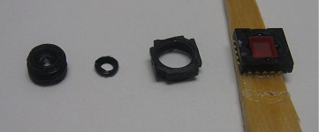
The bad news: The lens is on a threaded barrel for focal length adjustment, but the chips come from the factory pre-focused (probably for "infinity", though I haven't measured...think typical fixed-focus cellphone cam), and fixed in place with some kind of thread-locking adhesive.

The good news: I've worked out a pretty reliable procedure to unlock the threads and allow for adjustment. You can then adjust the focal distance for closer range (up to <1cm) by screwing the lens out (counterclockwise). Here's how to do it.

1) Find the seam where the main rectangular body (the part the lens screws into) mates with the base (the halves are held together by glue), and dab some epoxy (or other heat-safe glue) over the seam. The reason will become evident in the next steps.

2) Bake at the highest allowed storage temperature from the datasheet (60C?) for at least one hour.

3) Remove from oven and put a couple drops of isopropanol (or 91% rubbing alcohol) where the lens screws in, allowing it to flow into the threads. Let it sit for several minutes (if too much evaporates, add more). Although it does not dissolve the thread glue, the combination of heat and solvent seems to loosen its grip on the plastic considerably. Unfortunately it seems to have the same effect on the glue that holds the rest of the package together, hence the glue reinforcement earlier.

4) There is a pair of small indentations (notches/holes), one on either side of the square lens face. Clamp the part gently in a vise, and with some very needle-nosed pliers/tweezers inserted into these notches, very carefully rotate the lens counterclockwise. There may be a discernable 'snap' as the thread glue releases. Once this happens, you can unscrew the lens completely and (if desired) run an isopropanol-soaked Q-tip over the threads to dislodge any remaining glue.

I tried making a cast of the lens face and using that to rotate it, but there's very little face for it to grab onto - the tweezers worked better for me.

Some pictures of the results:

Image

Image 
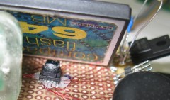
<--- resulting image

Image <---this is what can happen without reinforcing the main package glue :P
By Aerospace
#78693
Well, even though I said I was going to make headway on this about a month ago, as things go, I have only just finally begun to actually get some data out of it.

This camera is only useful to me if I can get the JPEG compression to work, so that is my end goal.

I still have a couple of kinks to work out of my firmware (timing issues w/ data transfer, etc) but I have been able to play with the register settings and I have found some things out...

1) PLL mode (0 is off, 1-F is on). It does make a difference what value you use (1-F). Higher values -> faster data clock. I believe JPEG needs at least 17 MHz data clock???

2) Both error flags (0xFA) are set as soon as I turn the JPEG compression on. With JPEG off only FULL_ERRN is set.

3) This is going to take awhile :)

I am reprogramming my PIC tomorrow, hopefully the update will fix the missing bytes I'm finding in my data.
By theawddone
#78922
I just received a few of these cameras, and just like others, they are useless to me unless I can use the JPEG output. It is somewhat disheartening to see so many issues with it, but I have not found any other COTS single chip solutions (other than the C328R, which has a boatload of other issues) so I hope for this to be the answer.

Hopefully some of the people in the past month who have been speaking of working with the JPEG output will respond back, and I will do the same, so we can attempt to collaborate.

FYI, I am using a PIC18F8722 at 25 MHz.
By Aerospace
#79002
I have just recently been pointed to the Micron (aptina) MT9D131, which is a SOC sensor with JPEG compression. However I am already pretty far along with the TCM8240, so I am going to try a little longer to see if I can get it working.

Currently I am trying to adjust the settings to make the error flags go away (I think one of them indicates an internal FIFO overflow, which means my compression is too low...)

I am getting data out, and while I can recognize some structures, things are missing and there is weird data that comes out before the SOI flag.

"000000000 8E 84 80 80 87 84 80 B6-90 81 80 80 B0 97 84 80
"000000010 A9 9C 81 80 80 A8 A5 81-80 A1 AA 82 80 80 80 A0
"000000020 A0 A0 A0 80 80 80 FF DB-00 84 00 10 0C 0E 0C 0A

Here is the first 3 lines of data that come out. Notice here the SOI flag is entirely missing, but sometimes the 'FF' portion comes through. And then it starts with the DQT structure, but the field length is wrong. I am going to try a different chip since the one I'm using now saw some abuse during initial fab.
By razvantgf
#79020
Anyone can give me a clue about this?
I set up the camera with the right voltages on IOVDD, PVDD, DVDD. Everything seems to be fine. The Dclk outputs the same frequency as the Extclk(I used the ccp module in pwm mode from a pic18f4620)
The problem is that a cannot get any acknowledge bit. I saw on oscilloscope SDA and SCL(pullups=10k) signals and they seem to be fine. I tried to slow them down a little bit thinking that they might be to fast , but in datash**t the maximum speed for i2c is 400 khz.
I accidently connect a few days ago SDA and SCL to some pins of the uC that where allready pulled up to 5v. Might this be the reason ? I'm confused because the Dclk outputs the same frequency as the Extclk input.
The i2c bus on the camera needs necessarly Extclck to work?(I'm thinikng that the frequency of the pwm is not proper, its about 5Mhz and not 6 the minimum)

Regards
By rask
#79106
Aerospace wrote:1) PLL mode (0 is off, 1-F is on). It does make a difference what value you use (1-F). Higher values -> faster data clock. I believe JPEG needs at least 17 MHz data clock???
Can you be a bit more specific? I mean, which DCLK frequencies do you get with the 1-F PLL settings and what was your input EXTCLK frequency?
Aerospace wrote:2) Both error flags (0xFA) are set as soon as I turn the JPEG compression on. With JPEG off only FULL_ERRN is set.
Please post register settings. Especially register 4.

Also, has anybody discovered a way of getting just 8 bits per pixel? Raw 8-bit bayer RGB in particular would be great.

I'm asking because I'll be trying to transfer data from this camera over a serial bus (SPI) at perhaps as little as 25 Mbit/s, so I need all the help I can get to reduce the output rate. Plan B is to convert RGB656 to RGB332 on the fly during parallel to serial conversion.

Page 25 of the datashit[1] says you must change a setting to operate the camera at 2.5 V instead of 2.8 V. Did anybody find it?

[1] Deliberate misspelling to avoid forbidden word filter.

EDIT: Fixed the quoting.
Last edited by rask on Sat Sep 26, 2009 12:13 pm, edited 1 time in total.
By Aerospace
#79162
First PLL:

Input clock = 10 MHz

PLL setting --> DCLK Freq (MHz)

1 --> 11.2
2 --> 12.5
3 --> 13.7
4 --> 15
5 --> 16.3
6 --> 17.6
7 --> 18.8
8 --> 21.1
9 --> 22.3
A --> 24.7
B --> 27.3
C --> 30
D --> 31.3
E --> 33
F --> 35

Also, while JPEG was on, if I set the PLL to 0, DCLK turned off completely
By Aerospace
#79164
Second Register settings:

Currently this is my initialization:

Address : Value

02 : 00
03 : 17 //DCLK = 18.8 MHz, Polarity inverted
04 : 50 //JPEG on, DOUT on, YUV sel, PICSIZE = full, Picmode = 1280x1024
05 : 00 //quarter speed (in JPEG, this doesn't affect DCLK, just the time it takes to output a full frame... possibly means different compression ratios)
1A : FF //H_Count -> 1023
1B : B3 //H_Count and V_Count adjust
1E : 6C //SP_Count (probably wrong)
1F : 09 //rest of SP_Count
58 : 20 //Exposure time (from other comments in this forum)
0B : 00 //White Line Off (from other comments as well)
0E : B0 //Change for different PIC size (probably wrong)
11 : 6A //same as 'OE'
14 : 33 //same as '11' and 'OE'
E6 : 08 //Read JPEG in 4 byte units (cant tell if this does anything)

Hope this helps move things along
By jye6305
#81810
Hello...can i have a wiring connection between MCU and TCM8240MD camera??? cos i have little confuse about the EXTCLK pin should connect to where pins of MCU???
By rask
#81821
razvantgf wrote:The problem is that a cannot get any acknowledge bit. I saw on oscilloscope SDA and SCL(pullups=10k) signals and they seem to be fine.
razvantgf wrote:I'm confused because the Dclk outputs the same frequency as the Extclk input.
The i2c bus on the camera needs necessarly Extclck to work?(I'm thinikng that the frequency of the pwm is not proper, its about 5Mhz and not 6 the minimum)
IIRC, it's been mentioned already that the camera just won't initialise at less than 6 MHz.
By rask
#81823
lastid wrote: I want to read barcodes with this camera. The minimum distance I want to achieve is in the range of 2cm-10cm.
I tried the oldest trick in the book on a USB webcam: Using a needle I made a tiny hole in a piece of paperboard and placed in front of the camera lens, flush to the camera. Then it reads barcodes fine at distances of 6 cm - 14 cm. It does however reduce the amount of light reaching the camera and the size of the image. You will likely want to experiment with different hole diameters and distances between hole and camera.
By rask
#81835
Aerospace wrote:02 : 00
03 : 17 //DCLK = 18.8 MHz, Polarity inverted
04 : 50 //JPEG on, DOUT on, YUV sel, PICSIZE = full, Picmode = 1280x1024
05 : 00 //quarter speed (in JPEG, this doesn't affect DCLK, just the time it takes to output a full frame... possibly means different compression ratios)
1A : FF //H_Count -> 1023
1B : B3 //H_Count and V_Count adjust
1E : 6C //SP_Count (probably wrong)
1F : 09 //rest of SP_Count
58 : 20 //Exposure time (from other comments in this forum)
0B : 00 //White Line Off (from other comments as well)
0E : B0 //Change for different PIC size (probably wrong)
11 : 6A //same as 'OE'
14 : 33 //same as '11' and 'OE'
E6 : 08 //Read JPEG in 4 byte units (cant tell if this does anything)
I too think you should first try without JPEG compression to see if you get a valid YUV image at all, especially with the modifications to HCOUNT, VCOUNT, SPCOUNT and such.
A possible aid in debugging the JPEG structure would be registers 0xF0:0xF1 Define Restart Interval to output a 0xFFDD DRI marker and periodic 0xFFD0..7 RST markers.
It looks like there are several registers related to JPEG in the 0xE9 to 0xFA area:
  • 0xE9 Define (download?) Y quantisation table gain(s)?
  • 0xEA Define (download?) U/V quantisation table gain(s)?
  • 0xEE V/U/Y quantisation table select?
  • 0xEF V/U/Y Huffmann table select AC/DC coefficient?
  • 0xF6:0xF7:0xF8 ENCDCNT = Encoder Discrete Cosine Transform?
By rask
#81841
ma4826 wrote:0x0B 0x00 White Line OFF
According to the datasheet, the default for register 0x0B was supposed to be 0x00. How nice. :-(
By omesa
#81921
Hi,
Regarding the JPEG mode.
if we know, in which mobile phone the camera modul was build in, we can analyze the I2C protocoll.
Maybe somebody know ??
Have a nice day
With best regards
Siegmar
By Dmitri
#84415
Hi all,

I'd like to make my comment on the Application Note for TCM8230MD by Justin L. Shumaker AKA Twingy

(http://www.arl.army.mil/arlreports/2009/ARL-TN-344.pdf) which I found extremely usefull.

He wrote on p.7:
The camera has a hexadecimal address of 0x60
In fact, 60 is the decimal value of its address which is 0x3C. See p.8 of TCM8230MD's datasheet.
There is only one command that must be sent to the camera for it to begin sending images—0x02.
In fact, it is IMHO all about the the second documented register whose address is 0x03. Setting DOUTSW bit to zero starts the cam.

BTW, you won't need a level shifter if you run your micro at 3VDC. It seems as if TCM8230MD inputs are 3V-tolerant.
  • 1
  • 16
  • 17
  • 18
  • 19
  • 20
  • 31