SparkFun Forums 

Where electronics enthusiasts find answers.

General project discussion / help
Did you make a robotic coffee pot which implements HTCPCP and decafs unauthorized users? Show it off here!
By JEBariffic
#180097
Salivations!

With the code below I'm trying to make my robot wheels spin individually clockwise, then counter clockwise.

The first wheel spins clockwise only. Second wheel spins as intended. See https://www.youtube.com/watch?v=yM2lqy_vczU

Most likely doing something dumb, but can't find the problem and thought I'd post up just to make sure I don't have a bad shield. Appreciate any help!
Code: Select all
#define CW  1
#define CCW 0
#define MOTOR_A 0
#define MOTOR_B 1
const byte PWMA = 3;  // PWM control (speed) for motor A
const byte PWMB = 11; // PWM control (speed) for motor B
const byte DIRA = 12; // Direction control for motor A
const byte DIRB = 13; // Direction control for motor B

void setup()
{
  setupArdumoto(); // Set all pins as outputs
  
  // Delay execution to give time to get out of the way
  delay(1000);
}

void loop() {
  driveArdumoto(MOTOR_A, CW, 100);
  delay(3000);
  stopArdumoto(MOTOR_A);
  delay(3000);
  
  driveArdumoto(MOTOR_A, CCW, 100);
  delay(3000);
  stopArdumoto(MOTOR_A);
  delay(3000);
  
  driveArdumoto(MOTOR_B, CW, 100);
  delay(3000);
  stopArdumoto(MOTOR_B);
  delay(3000);
  
  driveArdumoto(MOTOR_B, CCW, 100);
  delay(3000);
  stopArdumoto(MOTOR_B);
  delay(3000);
}


// driveArdumoto drives 'motor' in 'dir' direction at 'spd' speed
void driveArdumoto(byte motor, byte dir, byte spd)
{
  if (motor == MOTOR_A)
  {
    digitalWrite(DIRA, dir);
    analogWrite(PWMA, spd);
  }
  else if (motor == MOTOR_B)
  {
    digitalWrite(DIRB, dir);
    analogWrite(PWMB, spd);
  }  
}

// stopArdumoto makes a motor stop
void stopArdumoto(byte motor)
{
  driveArdumoto(motor, 0, 0);
}

// setupArdumoto initialize all pins
void setupArdumoto()
{
  // All pins should be setup as outputs:
  pinMode(PWMA, OUTPUT);
  pinMode(PWMB, OUTPUT);
  pinMode(DIRA, OUTPUT);
  pinMode(DIRB, OUTPUT);

  // Initialize all pins as low:
  digitalWrite(PWMA, LOW);
  digitalWrite(PWMB, LOW);
  digitalWrite(DIRA, LOW);
  digitalWrite(DIRB, LOW);
}
By Mee_n_Mac
#180138
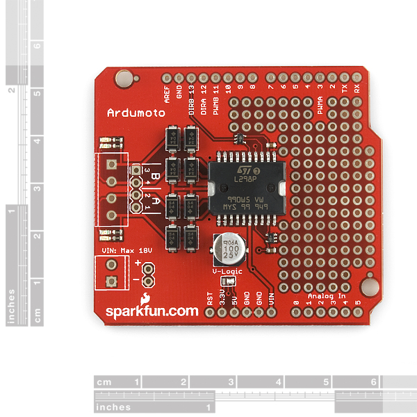
I don't see the SW as the problem so you need to look at the hardware. First thing is to see if the Direction signal for that motor is making it to the shield. If you have a DVM you can measure the voltage at pins 12 (DIRA) and 13 (DIRB) of the shield. You should see 5v for one direction, 0v for the other. If you don't have a DVM an LED and resistor can work instead.

If you see both pins changing state at the header then it's either a bad solder joint between the header and shield PCB or a bad Ardu shield. If you want you can probe the pins of the driver IC to see which. IN1 and IN2 are DIRA and DIRA(negated). IN3 and IN4 are DIRB and DIRB(negated). Those are pins 7, 9, 13 and 15 respectively.

If you don't see DIRA/B at the shield header then remove the shield and probe the Arduino pins 12 and 13. If it's not there then write a sketch that simply sets both pins to a LOW for 3 secs and then a HIGH for 3 secs, over and over. This will tell you if you've got a bad Arduino or bad code (somehow that I don't see).

But I'd bet on a bad solder joint.
By JEBariffic
#180141
Thanks for the troubleshooting help, mee. Testing pin 13 showed it wouldn't stay high. Not sure if fault was with arduino or the arduino header pins, but swapping out the arduino fixed the issue.

Now that I'm running, I noticed the motors supplied with the magician chassis (12866) don't spin at same rate, so the robot doesn't track straight. Adjusting the speed in the sketch can compensate, but it's far from a perfect. I wonder if all motors are inconsistent like that, or is this due to the low cost of that package?

Battery drain seems to be significant with these motor. I connected a ultrasonic sensor and it starts giving bad readings after ~ 15 minutes run time. Replacing batteries corrects the issue, for another 15 minutes :roll: Wondering if there is anyway to power motors separately to increase run time? Seems like if I could get a separate power to arduino, the sensor would last longer and bot could run longer (even if it slows).
By Mee_n_Mac
#180147
JEBariffic wrote:Thanks for the troubleshooting help, mee. Testing pin 13 showed it wouldn't stay high. Not sure if fault was with arduino or the arduino header pins, but swapping out the arduino fixed the issue..
Well that wasn't my 1st guess but whatever works ...
JEBariffic wrote:Now that I'm running, I noticed the motors supplied with the magician chassis (12866) don't spin at same rate, so the robot doesn't track straight. Adjusting the speed in the sketch can compensate, but it's far from a perfect. I wonder if all motors are inconsistent like that, or is this due to the low cost of that package?.
A bit of both I'd say. All DC motors will have a different Kv (RPM/volt), cheap ones will show a wider variance. Also the wheels will be slightly different diameters. All adding up to non-straight motion. You'll have to take some measurements and come up w/some compensation factors.
JEBariffic wrote:Battery drain seems to be significant with these motor. I connected a ultrasonic sensor and it starts giving bad readings after ~ 15 minutes run time. Replacing batteries corrects the issue, for another 15 minutes :roll: Wondering if there is anyway to power motors separately to increase run time? Seems like if I could get a separate power to arduino, the sensor would last longer and bot could run longer (even if it slows).
I'd have to look at the schematic but I'd bet there's some way to power the motors separately from the Arduino.
By JEBariffic
#180148
I love the price of the magician chassis and motors, but in using it as a teaching platform, I think the variance in motors (and tracking problems possibly coming from the caster and wheels) would make for some disappointed students. Shame because the redbot package is really nice both feature and cost wise.

My thinking now is to bite the bullet and go with a servo based platform. They seem to be more expensive, but if I understand correctly, offer greater motor control.
By Mee_n_Mac
#180150
Well there is some way to separately power the motors but it's a bit irreversible. A voltage named Vin comes in on the Arduino barrel jack. It goes to the onboard regulator and also to pin Vin on the header to the shield. This also goes to power the motors and to the pads you can see below on the shield, labeled Vin and also +/-. So if you cut off the header pin from the shield to the Vin pin on the Arduino, the two will be separated. You can use different batteries at different voltages to run them.

Image
By Mee_n_Mac
#180151
JEBariffic wrote:I My thinking now is to bite the bullet and go with a servo based platform. They seem to be more expensive, but if I understand correctly, offer greater motor control.
I'm not sure you'd fix the problem. You'll trade off Kv variance for variance in the servo reference. Instead, depending on your students and what you're trying to teach them, you can add a feedback system to the open loop chassis/motors and demonstrate why closed loop systems are used.

The old chassis used opto-detectors and cogs for feedback. Don't do that !!
https://forum.sparkfun.com/viewtopic.ph ... to#p177795

The new ones have, IIRC, Hall effect sensors. Hopefully they work better.
By JEBariffic
#180170
I like the vin split idea. Thank you! I think it'll be worth the effort.

Yes, the Red Bot does offer Hall sensors as an add on. Will research then. They're shown attached by zip ties which seems a bit iffy (https://learn.sparkfun.com/tutorials/re ... 1421265888) but price is still under budget.

And that budget is $100, ideally. Giving a summer class for middle to high-school kids. Two four-hour classes.
Wish I could find a bot kit that:
- runs on arduino uno that can be used stand alone as well as for robot
- can run on low carpet (four wheels or treads would be great, but I've not found any at the $100 price point)
- runs straight enough so that programming routes is a legitimate exercise
- can include either a bump or ultrasonic sensor at budget
- has enough extra onboard space for adding additional sensors

Have not been able to find anything that hits all those points.
By tdelker
#180449
My issue with the magician chassis is that the wheels wobble on the axle attached to the motor and don't run true. I can straight it out, but after a few turns they are out of true again, causing it to turn too fast in on direction. Anyone have a solution?