SparkFun Forums 

Where electronics enthusiasts find answers.

General project discussion / help
Did you make a robotic coffee pot which implements HTCPCP and decafs unauthorized users? Show it off here!
By JuanM
#172331
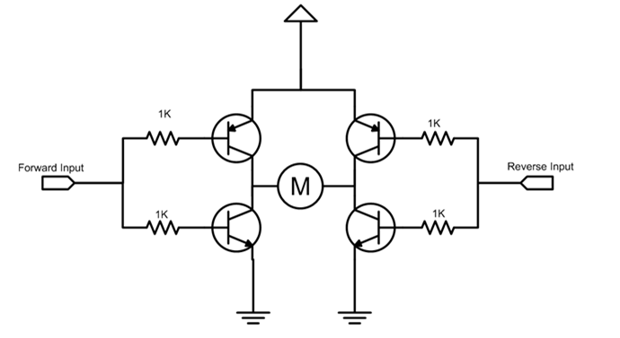
Is there anyway for me to control an DC motor with just 2 wires, reversing the polarity on them, and considering that the voltage between them is not enough to actually drive the motor? I though of something like and H-bridge made out of transistors, controled by another group of transistors, but I'm not sure of how I could do it.
By waltr
#172347
You describe an H-bridge. So google search "h-bridge" to see how to do this
By JuanM
#172349
Image
An H-Bridge needs more than 2 wires, at least, one for each switch/transistor + ground.
By Mee_n_Mac
#172352
Here's a common low power dual H bridge IC.
http://www.ti.com/lit/ds/symlink/l293d.pdf
If you leave the enable tied high, you use only 2 wires from your controller and only 2 wires to the motor. If you want forward, reverse and stop ... you have to have 2 wires ... or a serial interface.
By JuanM
#172353
So, here's the thing… I wanted to know if there's a way to build the thing out of transistors
By Mee_n_Mac
#172354
JuanM wrote:So, here's the thing… I wanted to know if there's a way to build the thing out of transistors
In a word, yes ... that what's inside any H bridge IC. What's needed that I don't know is what you want for a motor voltage, what kind of power delivered, what your 2 wires can source and sink for current, what voltages they are and perhaps a few other things. You'll probably need some resistors too. Google shows this as perhaps the simplest configuration.
Image
For that matter you could make a really slow one out of 2 DPDT relays.
User avatar
By Ross Robotics
#172355
http://goo.gl/BdhdMF

Mac beat me to it, but Google has hundreds of examples.
By skimask
#172359
codlink wrote:Mac beat me to it, but Google has hundreds of examples.
Correction:

Google has millions of examples.

:D
By JuanM
#172365
Thank's guys! I did google it, but didn't find the right circuit. Anyway, this helped me out :D
By markaren1
#172366
Assume you are driving the circuit made of transistors above.

Connect a logic inverter between fwd and rev inputs, with the input on fwd.

On the fwd input, now apply a PWM waveform maybe 1kHz.

With the PWM set to 50:50, the average difference between the motor terminals is 0v, so it is stationary.

Set PWM to 10:90 and the motor will rotate fwd.

Set PWM to 90:100 and the motor will rotate rev.

Other mark/space ratios adjust speed with 100:0 and 0:100 being flat out, 50:50 will always be stationary.

-mark
By Mee_n_Mac
#172382
Logic highs on both inputs will also be off ... and a brake as both NPNs will be conducting, thus shorting both motor leads to ground. Logic lows on both inputs has the same off and braking effect. One big disadvantage of using the simple circuit above is that the transistor turn on and turn off times are not matched and so, w/o any delay between switching logic states, you may have the PNPs and NPNs on at the same time for some "brief" period of time. That shorts the Vcc to ground and no good can come from that.