SparkFun Forums 

Where electronics enthusiasts find answers.

General project discussion / help
Did you make a robotic coffee pot which implements HTCPCP and decafs unauthorized users? Show it off here!
By jc27
#168270
Here is the newest code
Code: Select all
#include <Servo.h>
int button1 = 4;
int press1 = 0;
int button2 = 5;
int press2 = 0;
Servo servo1;
int pos = 0;


void setup()
 {
  pinMode(button1, INPUT);
  pinMode(button2, INPUT);
  servo1.attach(9);
  Serial.begin(9600);
  servo1.write(10);
  

 }

void loop()
 {
  if ( (digitalRead(button1) == HIGH) && (pos == 10) )
   {
    for (pos = 10; pos < 100; pos +=1)
     {
      servo1.write(pos);
      Serial.println(pos);
      delay(15);
     }
   }

  if ( (digitalRead(button2) == HIGH) && (pos == 100) )
   {
    for (pos = 100; pos > 10; pos -=1)
     {
      servo1.write(pos);
      Serial.println(pos);
      delay(15);
     }
   }
 }
I got excited because it worked the second time it tried it, but then nothing. The serial monitor shows nothing, so I was thinking that it wasn't getting a signal from the rf transmitter. I connected the transmitter to a couple LEDs, and they worked (but I think I need new batteries in the key fob). When I upload the code the servo starts humming and doesn't stop, so I don't know what's going on with that. I am not sure how the 10k resistors should get connected to the inputs of the arduino; rf output to resistor to arduino, or resistor to ground and arduino with the rf input in series with that. I didn't know how it should get hooked up with the resistors so I connected an input pin to a 5v source and nothing, no rotation and nothing on the serial monitor. I tried that with both input pins and neither did anything. The servo works because I can load the sweep example leaving the servo input the same as with my code (pin 9) and it works fine, so the servo is not the problem.
I was thinking that the receiver/transmitter was the problem since its so sporadic in lighting the LEDs, but why wouldn't the servo rotate if I connected one of the arduino input pins (either 4 or 5) to a 5v source (not from the arduino but a USB breadboard kit that I bought from here)? If the pins get a 5v source, shouldn't the servo rotate? The one time it did work the serial monitor did show it move from 0 to 90, but I didn't look so see what it said when I got it to rotate back to 0 from 90, I was excited it was working and wasn't paying attention, and now it does absolutely nothing, other than create a humming servo.
Is there another small RF transmitter/receiver combo that would do what I am looking for? Maybe its the current ones I'm using, like you mentioned in an earlier post. I need it to be as small as possible because this will be going into a costume helmet and they don't provide a lot of extra room.
I was planning on running the servo off of an Adafruit trinket, but its looking like that isn't going to work so I may have to use an arduino nano or micro. I think the code will work, I just need to figure out if its the code, my input wire connections, or the receiver/transmitter combo.
By Mee_n_Mac
#168280
I would recommend that you only change 1 thing at a time. Look at your for() loops now vs before. The conditional tests have slightly changed (and I don't mean pos set to 10/100 vs 0/90).
Code: Select all
for (pos = 10; pos < 100; pos +=1)
for (pos = 100; pos > 10; pos -=1)
Before they were ...
Code: Select all
for (pos = 0; pos <= 90; pos +=1)
for (pos = 90; pos >= 0; pos -=1)
As far as button pushes being "seen" (or not), add in a couple more prints saying "button XYZ pressed" where they'll show if the Arduino saw them. Learning to debug code will teach you how to write code.

FWIW a Trinket should work but you will need to use an older servo library and alter the loop() code ever so slightly.

ps - What 10k resistors ? I don't see any need for resistors.
By jc27
#168282
I thought that the <= and >= in the for statements didn't allow it to rotate since the servo's position wasn't equal to 9 or 0. The "button x pressed" should go in after the for statements right? I will try it again tonight with the new print lines and the for statements in their original form and see what happens.
By Mee_n_Mac
#168384
OK I now see 2 problems. Look at these statements from your last posted code;
Code: Select all
int pos = 0;

void setup()
 {
  servo1.write(10);
 }

void loop()
 {
  if ( (digitalRead(button1) == HIGH) && (pos == 10) )
    {
      for (pos = 10; pos < 100; pos +=1)
Tell how the conditions to get to increment pos will ever be met w/pos initialized as it is ?

Also a for loop checks the condition (pos < 100) at the top/start of each loop/iteration. If the condition is met, the code is run and the pos +=1 is executed, at the bottom of the loop. If the condition is NOT met, the code is not run and the pos +=1 is not executed ... the for loop is just exited at it's top.

So imagine the initialization error is fixed and pos = 10 and button1 is pushed. The for loop sets pos = 10, it passes the condition (10 < 100) and the loop is run. Pos goes to 11 and then the loop is repeated. When pos = 99 the loop is run and at the bottom pos increments to 100. At the top the condition is not met and the servo is left at 99 but pos = 100. This at least allows the later test to pass.
Code: Select all
if ( (digitalRead(button2) == HIGH) && (pos == 100) )
My for loop condition test (pos >= 100) gets the servo commanded to 100 but leaves pos = 101 when the for loop exits. That ain't good either !

So I'd use a different index, not pos, in each for loop (if the servo error of 1 deg matters).
Code: Select all
if ( (digitalRead(button1) == HIGH) && (pos == 10) )
   {
    for (int i = 0; i < 99; i ++)
     {
      pos ++;  //i goes from 0 to 98 in the loop, loop runs 99 times, so pos will go from 10 to 100
      servo1.write(pos);
      Serial.println(pos);
      delay(15);
     }
   }
By Mee_n_Mac
#168395
jc27 wrote:I will rewrite it with your suggestions. I will also put comments on things things I change that I am unsure of.
Comments are good. And you read mine in the code above it'll be obvious I've got the if() conditional value wrong and what value it should be. :oops: :doh:
By jc27
#168614
Here is the new code:
Code: Select all
#include <Servo.h>
int button1 = 4;
int press1 = 0;
int button2 = 5;
int press2 = 0;
Servo servo1;
int pos = 0; // I'm resetting everything to 0-90 degree rotation

void setup()
{
  pinMode (button1, INPUT);
  pinMode (button2, INPUT);
  servo1.attach (9);
  Serial.begin(9600);
  servo1.write (0); // set start position to 0 degrees?
}

void loop()
{
  if ((digitalRead(button1)) == HIGH && (pos == 0)) // 0 to 90 rotation
  {
    for (int i = 0; i < 90; i ++) // using your recommendation but I thought the i is supposed to go in there
    {
      pos ++;
      servo1.write(pos);
      Serial.println(pos);
      delay(15);
    }
  }
  if ((digitalRead(button2)) == HIGH && (pos == 90))
  {
    for (int i = 90; i > 0; i --) // same as above not sure if its correct
    {
      pos --; // is this correct?
      servo1.write(pos);
      Serial.println(pos);
      delay(15);
    }
  }
}
      
I did some reading and read some posts on the Arduino forum and I thought that changing the for statement might help. It seems to work, but i think that I am drawing too much power from the computer USB plugs. I got an overcurrent message and it made my backlit keyboard crap out. I used 10k resistors to keep the pins LOW, and used the 5v from the usb unit as the high and it rotated fine. I may have to go with a stronger servo, it was a bit jerky, I'm thinking that I am pushing the torque limit, so I am going to do a little searching for a little bit stronger one that is close to the same size.
I am thinking since I had the servo,and the reciever running off of the USB board, that is why I couldn't get it to work using the transmitter/receiver system. The only way it would rotate was when I used the straight 5v from the USB board and connected it to one of the input pins.
Now it seems I'm going to have a power problem. I found a lithium 9v that has 1400mAh, which should work, but I don't think that it will last very long. It looks like the servo draws around 300mA, so theoretically the lithium 9v should be enough. I have a DC/DC converter that puts out 5v and 1.5a, so that should be good. Would it be better to go with a battery pack? I'm limited on space so using 1 or 2 batteries is about the most I think I can get away with. I am going to try another idea I have just to see if powering the receiver with its own 5v supply (a separate source not in the current circuit. I will need to connect that ground to the servo circuit ground though correct?)
By Mee_n_Mac
#168663
jc27 wrote: Now it seems I'm going to have a power problem. I found a lithium 9v that has 1400mAh, which should work, but I don't think that it will last very long. It looks like the servo draws around 300mA, so theoretically the lithium 9v should be enough. I have a DC/DC converter that puts out 5v and 1.5a, so that should be good. Would it be better to go with a battery pack?
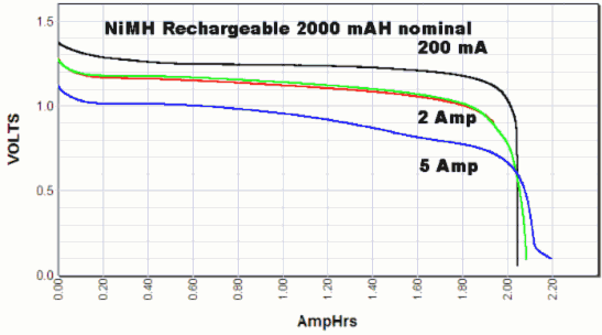
FWIW the 1400 mAh rating is the energy the battery contains, not the current capacity. A 9v PP3 size lithium might last 1400 hours with an average load of 1 mA. Or 140 hrs when supplying 10 mA. But I think the peak current rating is 120-150 mA. You'd be better off w/4 rechargable Nimh AAs to run your servo, etc...
By jc27
#168673
Space is going to be small so a large battery pack won't work. There are a few kits that do close to the same thing as this kit is going to do, and they run off of plain 9v (although one kit may run off of 9 connected in parallel but I'm not sure in that one).
If I can get one 9v to power everything for even a little bit ( the kit isn't going to be used continuously, just occasionally), that may be my only option due to space constrains.
By jc27
#168675
I found a 6AA battery holder and 1.2v 2500mAh Ni-mh AA batteries. 6 in series would give me 7.2 volts, which I would step down to 5v with the regulator.
The transmitter has it's own power source so it won't be in the servo & receiver circuit.
By jc27
#168703
I'm going to check the minimum voltage for the servo and see if it will work with the 4.8v from the batteries. It would be great if everything could work off of one battery pack. It would make designing the board much easier.
By jc27
#169080
I'm going to try everything out with a 5v regulated power supply maybe tonight to see if everything works like I want it to. Here is another question, is it possible to run the rotation code with a single ATtiny85? I have the USB ATtiny programmer you sell as well as a few spare ATtiny chips, so I was wondering if it was possible. How much would I have to change the code as it stands now, and do you know of a smaller transmitter/receiver combo than what I am using now that would work? Im trying to get this circuit as small as possible due to the space constraints inside of the helmet.