SparkFun Forums 

Where electronics enthusiasts find answers.

General project discussion / help
Did you make a robotic coffee pot which implements HTCPCP and decafs unauthorized users? Show it off here!
By Mee_n_Mac
#163887
blf wrote:
Mee_n_Mac wrote:I assume this is it's own board - i.e. it's not a shield like this one: https://www.sparkfun.com/products/10878

If I go with the El Escudo, I need the Arduino, too, right?
Correct, the standalone board is effectively an Arduino plus the AC switching circuitry. You need a USB to serial adapter to program it. If you already have an Arduino to dedicate to the project, then you could use the shield (plus Arduino). Note the following caution on the shields product page;
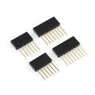
*Comes without headers, soldering required
... so you need these as well as the inverter and EL wire.
https://www.sparkfun.com/products/10007
Image
By blf
#163962
I really like the El Sequencer. I'm not much of a solder-et (is that a word?)

So, it looks like I can buy the El wire with JST connectors. They plug in. The inverter also plugs in and I program it. Do I need a separate battery source to power the board or does it somehow slip off some dc power before inverting it? Also, looks like one inverter is all I need. So If I want to power 8 strands, what size inverter should I use? And I jsut need to make sure I need one with JST connections - to avoid the soldering issue.....
By Mee_n_Mac
#163969
The El Sequencer board can get it's power from whatever your source is for the inverter. The table in this tutorial for the shield also applies to the El Sequencer. It seems to all hinge on how many ft of EL wire you run; many feet means a large 12v inverter, less ft allow you to use the 3v inverter. This is also discussed below.
https://www.sparkfun.com/tutorials/353
Also read through all the comments on the El Sequencer product page, there's good info there.
By blf
#163973
Great! I have been doing the reading, thanks!

I will probably need the 12v inverter, but it doesn't look like it's battery operated. Also, I don't see any info on how to power the ElSeq board.
By Mee_n_Mac
#163975
blf wrote: Also, I don't see any info on how to power the ElSeq board.
The MCU on the board gets it's power from a separate (from the LM317) 3.3v regulator that gets it's power from either the battery connector or "USB-5V", aka the pin labelled 5v in the FTDI area. You select which is used via switch SW1.

The inverter may get it's DC power from the board as discussed below;
R0B0T1CS | about 9 months ago * 1
Ckt Diagram indicates:

Batt Min is “4.8V if using LM317 regulator at default 3.3V DC out to iverter”

This page indicates:
“Can be powered by a 3.7V Lipo battery (using 3V inverter), or an external 3.3V to 16V supply (using 3V or 12V inverter)”

Which is it? If it does in fact require >3.7V, please use a Vreg with lower dropout on the next revision!

Also, why do both this page and the ckt diagram suggest the use of the “5V FTDI BOB” when the microcontroller is run at 3.3V?

Which Should be used?

MikeGrusin | about 9 months ago * 2

It’s both. This board is pretty versatile, and can be reconfigured for various power sources and inverter choices.

If you wish to use a 5V-12V supply and the 3V inverter, the LM317 regulator will provide 3.3V for the inverter.

If you wish to use a 3.7V Lipo supply and the 3V inverter, you can bypass the LM317 regulator and send 3.7V straight to the inverter.

If you wish to use a 12V supply and the 12V inverter, you would also bypass the LM317 and send 12V straight to the inverter.

The tutorial at the top of this page has more information and a table of the various configurations you could use.

To answer your other questions:

The reason we’re using a 1.5V dropout regulator is that we wanted the inverter regulator to be able to handle up to 1.5A for very large inverters. As the inverter isn’t picky about the exact input voltage (e.g. the 3V inverter is quite happy running on a Lipo’s unregulated 3.7V), the extra expense of a high-current LDO wasn’t warranted.

The reason we spec’d a 5V FTDI on a 3.3V system, is that if you’re going to use the FTDI to power the board + inverter, the 5V FTDI can supply up to 500mA whereas the 3.3V FTDI can only supply 50mA.
By Mee_n_Mac
#163988
See if this diagram helps. SJ1 is a "solder jumper" to bypass the LM317, if you want to make the connection you add a blob of solder to electrically re-connect the "broken path".
(click on to open)
ELsequencerPwrPaths.jpg
You do not have the required permissions to view the files attached to this post.
By blf
#163991
Mee_n_Mac wrote:
blf wrote: Also, I don't see any info on how to power the ElSeq board.
The MCU on the board gets it's power from a separate (from the LM317) 3.3v regulator that gets it's power from either the battery connector or "USB-5V", aka the pin labelled 5v in the FTDI area. You select which is used via switch SW1.
So, if I am reading this correctly, I can use this battery that I already have: https://www.sparkfun.com/products/339 to power the board. And I can purchase the 12V El inverter https://www.sparkfun.com/products/10469 to drive the El Wire. But the diagram appears to have only one power source - the 3-12V Batt. So do I use the 12V inverter to power both? But I thought I read that I can't power the board and the EL off the same source, but it look like I can?
By Mee_n_Mac
#163994
That's a 3.7v battery so you can't use it to power the 12v inverter. It can be used to power the board, just plug it into the battery connector. See the summary table ;
https://www.sparkfun.com/tutorials/353
ELsequencerPwrSummary.jpg
If that battery was a "12v" (sold as 11.1v LiPo) then, per the above, you could plug it into the battery connector, solder blob SJ1, and then plug the inverter "DC in" to the inverter DC pwr connecter to power the inverter.
https://www.sparkfun.com/products/10470

Alternately you can just get another battery to run the inverter separately and use both batteries.
You do not have the required permissions to view the files attached to this post.
By Mee_n_Mac
#163996
blf wrote: Is the 12v inverter battery operated?
It runs off of "12v", it doesn't know or care where it comes from. It's just a question of battery size and life/runtime.
By Mee_n_Mac
#163997
BTW if you use the 8 channels to drive 8 poodles and only ever have 1 poodle on at a time ... do you really need the 12v inverter ?