SparkFun Forums 

Where electronics enthusiasts find answers.

General project discussion / help
Did you make a robotic coffee pot which implements HTCPCP and decafs unauthorized users? Show it off here!
By RossWaddell
#183105
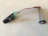
I'm using a SOTC test clip wired up to connect to my PIC programmer (see photo below) and this seems to work well to program SMD PICs off board (as long as I'm careful not to bend the leads). Can I use this to reprogram the SMD PIC when its soldered in place on the PCB? I'm not sure if the clip will make a good enough connection once the PIC is soldered down, and I'm not sure once my other components are also soldered in whether that will affect the ability to reprogram the chip.

Image

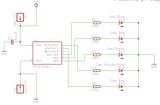
This is the schematic for my board - a typical 0.1uF cap between +5V & GND pins with series resistors & LEDs.

Image
By skimask
#183108
Probably have to 'hold' the test clip on the PIC while programming is taking place...if only to make sure you've got a solid connection.
And the resistor/LEDs may load down the PGC/PGD lines too much to let the programmer function properly as well.
Desolder the resistors and/or add a jumper to those particular lines... I don't see why it won't work.
Read the datasheets. Talks all about putting extra loads on PGC/PGD and the effects on ICSP.
By RossWaddell
#183113
skimask wrote:Probably have to 'hold' the test clip on the PIC while programming is taking place...if only to make sure you've got a solid connection.
And the resistor/LEDs may load down the PGC/PGD lines too much to let the programmer function properly as well.
Desolder the resistors and/or add a jumper to those particular lines... I don't see why it won't work.
Read the datasheets. Talks all about putting extra loads on PGC/PGD and the effects on ICSP.
Thanks skimask. By "add a jumper to those particular lines" do you mean adding something like a low-profile DIP switch (e.g. http://www.digikey.ca/product-search/en ... s=679-3565) so that the ICSP pins can be switched to GND (or left hanging) for in-circuit programming? Looking at the 12F683 data sheet, it says pins 6 & 7 are the ICSP pins, so just those 2 need to be jumpered?
By skimask
#183117
Pretty much. DIP switches, 2 pin jumper, leave the resistors out...whatever works.
You just don't want extra loads on the ICSP pins that the programmer doesn't expect and/or can't handle.
Look at the PICKIT2 user's manual datasheet. Talks all about that sort of thing.


Have I put together circuits with stuff on the ICSP pins and did it work without any extra jumpers or otherwise? Yes.
Was it the correct way to do things? No. And if it wouldn't have worked, I would've known exactly where to go to fix the problem.
By RossWaddell
#183121
skimask wrote:Pretty much. DIP switches, 2 pin jumper, leave the resistors out...whatever works.
You just don't want extra loads on the ICSP pins that the programmer doesn't expect and/or can't handle.
Look at the PICKIT2 user's manual datasheet. Talks all about that sort of thing.


Have I put together circuits with stuff on the ICSP pins and did it work without any extra jumpers or otherwise? Yes.
Was it the correct way to do things? No. And if it wouldn't have worked, I would've known exactly where to go to fix the problem.
Thanks again skimask!
By lyndon
#183125
It should work. I have a small board with a Tiny13 that I program with a SOIC test clip. As long as you leave enough room for the clip it works just fine.