- Thu Sep 01, 2016 5:08 am
#191481
EDIT: I was actually able to solve my problem by moving the 10k resistors to the gate of the MOSFETs instead of the Drain.
Hello everyone, I am working on a project that makes an LED Strip respond to music using the MSGEQ7 chip. Forgive me if this a foolish question but I am having an issue where every other segment of the led strip is always on and unresponsive. (i.e. only half of the strip is blinking to the music)
I am using these LED Strips (HML 5M SMD 3528 Flexible LED RGB Strip): http://www.gearbest.com/led-strips/pp_1 ... tml?wid=21
I have followed this guide: http://www.instructables.com/id/Blinkin ... y-of-Musi/
I followed this fritzing diagram:
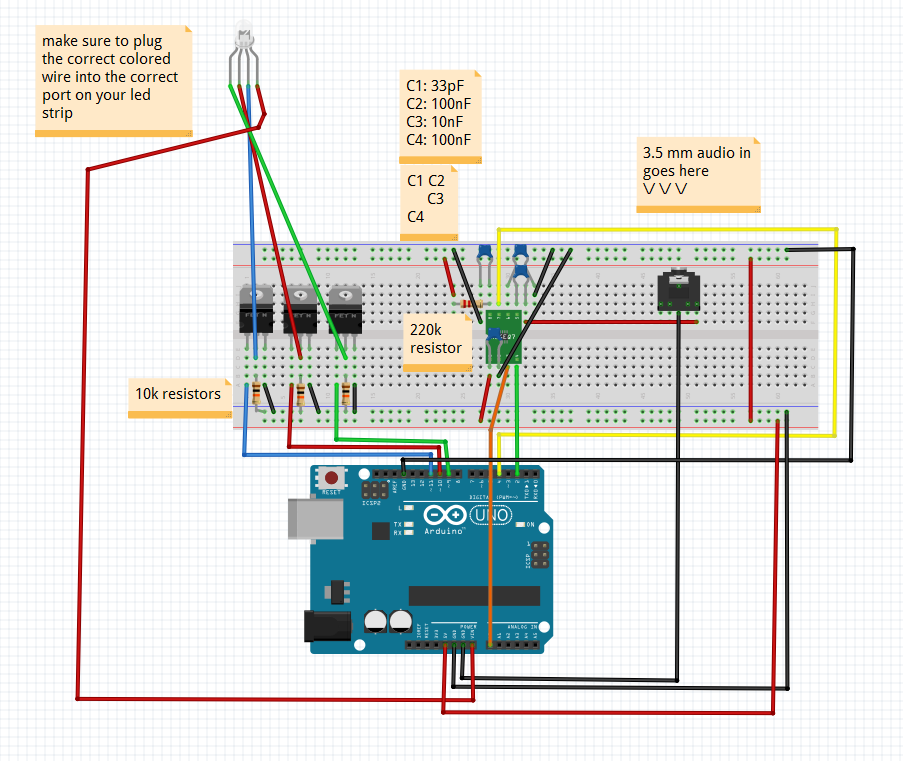
except that I have an external 12V 5 A DC power supply plugged into the power rail with the MOSFETs and the 12V lead of the led strip pluged into the positive terminal of that power supply.
I don't think my strips are faulty because they behave normally when I use the IR controller that they came with as opposed to my arduino.
Here is the code I was testing with:
The external 12V 5A power supply shares a common ground with the MOSFETs and Arduino. Am I wiring that correctly? I am also using an Arduino Due by the way.
Also, I commented out the line that set the analog reference voltage because I was getting a compiling error. Not sure if that affected anything.
Hello everyone, I am working on a project that makes an LED Strip respond to music using the MSGEQ7 chip. Forgive me if this a foolish question but I am having an issue where every other segment of the led strip is always on and unresponsive. (i.e. only half of the strip is blinking to the music)
I am using these LED Strips (HML 5M SMD 3528 Flexible LED RGB Strip): http://www.gearbest.com/led-strips/pp_1 ... tml?wid=21
I have followed this guide: http://www.instructables.com/id/Blinkin ... y-of-Musi/
I followed this fritzing diagram:
except that I have an external 12V 5 A DC power supply plugged into the power rail with the MOSFETs and the 12V lead of the led strip pluged into the positive terminal of that power supply.
I don't think my strips are faulty because they behave normally when I use the IR controller that they came with as opposed to my arduino.
Here is the code I was testing with:
Code: Select all
The strips are common anode and the transistors I am using are N-Channel MOSFET 60V 30A : https://www.sparkfun.com/products/10213/* David Wang
Code that takes audio input from a 3.5mm cable
and flashes an LED strip based on the frequency
of the music.
HUGE thanks to the arduino community
If you see your code here, I owe you my gratitude
*/
// MODIFY SETTINGS TO WHAT EVER WORKS BEST FOR YOU!
int analogPin = 0; // MSGEQ7 OUT
int strobePin = 2; // MSGEQ7 STROBE
int resetPin = 4; // MSGEQ7 RESET
int spectrumValue[7];
// MSGEQ7 OUT pin produces values around 50-80
// when there is no input, so use this value to
// filter out a lot of the chaff.
int filterValue = 80;
// LED pins connected to the PWM pins on the Arduino
int ledPinR = 10;
int ledPinG = 9;
int ledPinB = 11;
void setup()
{
//Serial.begin(9600);
// Read from MSGEQ7 OUT
pinMode(analogPin, INPUT);
// Write to MSGEQ7 STROBE and RESET
pinMode(strobePin, OUTPUT);
pinMode(resetPin, OUTPUT);
  // Set analogPin's reference voltage
  //  analogReference(DEFAULT); // 5V
// Set startup values for pins
digitalWrite(resetPin, LOW);
digitalWrite(strobePin, HIGH);
}
void loop()
{
// Set reset pin low to enable strobe
digitalWrite(resetPin, HIGH);
digitalWrite(resetPin, LOW);
// Get all 7 spectrum values from the MSGEQ7
for (int i = 0; i < 7; i++)
{
digitalWrite(strobePin, LOW);
delayMicroseconds(30); // Allow output to settle
spectrumValue[i] = analogRead(analogPin);
// Constrain any value above 1023 or below filterValue
spectrumValue[i] = constrain(spectrumValue[i], filterValue, 1023);
// Remap the value to a number between 0 and 255
spectrumValue[i] = map(spectrumValue[i], filterValue, 1023, 0, 255);
// Remove serial stuff after debugging
//Serial.print(spectrumValue[i]);
//Serial.print(" ");
digitalWrite(strobePin, HIGH);
}
//Serial.println();
// Write the PWM values to the LEDs
// I find that with three LEDs, these three spectrum values work the best
analogWrite(ledPinR, spectrumValue[1]);
analogWrite(ledPinG, spectrumValue[4]);
analogWrite(ledPinB, spectrumValue[6]);
}The external 12V 5A power supply shares a common ground with the MOSFETs and Arduino. Am I wiring that correctly? I am also using an Arduino Due by the way.
Also, I commented out the line that set the analog reference voltage because I was getting a compiling error. Not sure if that affected anything.
Code: Select all
Any thoughts or suggestions? Thanks for your help! // Set analogPin's reference voltage
// analogReference(DEFAULT); // 5V