Let me first apologize for the format of this post. This is my first attempt to incorporate code and images utilizing the hotlink at the top of the message . . . fingers crossed.
1) First, I utilized the following code as downloaded without any modifications:
Code: Select all/* SFE_TSL2561 library example sketch
This sketch shows how to use the SFE_TSL2561
library to read the AMS/TAOS TSL2561
light sensor.
Product page: https://www.sparkfun.com/products/11824
Hook-up guide: https://learn.sparkfun.com/tutorials/getting-started-with-the-tsl2561-luminosity-sensor
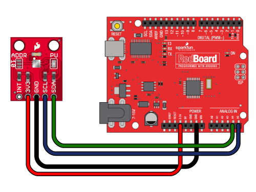
Hardware connections:
3V3 to 3.3V
GND to GND
(WARNING: do not connect 3V3 to 5V
or the sensor will be damaged!)
You will also need to connect the I2C pins (SCL and SDA) to your Arduino.
The pins are different on different Arduinos:
SDA SCL
Any Arduino "SDA" "SCL"
Uno, Redboard, Pro A4 A5
Mega2560, Due 20 21
Leonardo 2 3
You do not need to connect the INT (interrupt) pin
for basic operation.
Operation:
Upload this sketch to your Arduino, and open the
Serial Monitor window to 9600 baud.
Have fun! -Your friends at SparkFun.
Our example code uses the "beerware" license.
You can do anything you like with this code.
No really, anything. If you find it useful,
buy me a beer someday.
V10 Mike Grusin, SparkFun Electronics 12/26/2013
*/
// Your sketch must #include this library, and the Wire library
// (Wire is a standard library included with Arduino):
#include <SFE_TSL2561.h>
#include <Wire.h>
// Create an SFE_TSL2561 object, here called "light":
SFE_TSL2561 light;
// Global variables:
boolean gain; // Gain setting, 0 = X1, 1 = X16;
unsigned int ms; // Integration ("shutter") time in milliseconds
void setup()
{
// Initialize the Serial port:
Serial.begin(9600);
Serial.println("TSL2561 example sketch");
// Initialize the SFE_TSL2561 library
// You can pass nothing to light.begin() for the default I2C address (0x39),
// or use one of the following presets if you have changed
// the ADDR jumper on the board:
// TSL2561_ADDR_0 address with '0' shorted on board (0x29)
// TSL2561_ADDR default address (0x39)
// TSL2561_ADDR_1 address with '1' shorted on board (0x49)
// For more information see the hookup guide at: https://learn.sparkfun.com/tutorials/getting-started-with-the-tsl2561-luminosity-sensor
light.begin();
// Get factory ID from sensor:
// (Just for fun, you don't need to do this to operate the sensor)
unsigned char ID;
if (light.getID(ID))
{
Serial.print("Got factory ID: 0X");
Serial.print(ID,HEX);
Serial.println(", should be 0X5X");
}
// Most library commands will return true if communications was successful,
// and false if there was a problem. You can ignore this returned value,
// or check whether a command worked correctly and retrieve an error code:
else
{
byte error = light.getError();
printError(error);
}
// The light sensor has a default integration time of 402ms,
// and a default gain of low (1X).
// If you would like to change either of these, you can
// do so using the setTiming() command.
// If gain = false (0), device is set to low gain (1X)
// If gain = high (1), device is set to high gain (16X)
gain = 0;
// If time = 0, integration will be 13.7ms
// If time = 1, integration will be 101ms
// If time = 2, integration will be 402ms
// If time = 3, use manual start / stop to perform your own integration
unsigned char time = 2;
// setTiming() will set the third parameter (ms) to the
// requested integration time in ms (this will be useful later):
Serial.println("Set timing...");
light.setTiming(gain,time,ms);
// To start taking measurements, power up the sensor:
Serial.println("Powerup...");
light.setPowerUp();
// The sensor will now gather light during the integration time.
// After the specified time, you can retrieve the result from the sensor.
// Once a measurement occurs, another integration period will start.
}
void loop()
{
// Wait between measurements before retrieving the result
// (You can also configure the sensor to issue an interrupt
// when measurements are complete)
// This sketch uses the TSL2561's built-in integration timer.
// You can also perform your own manual integration timing
// by setting "time" to 3 (manual) in setTiming(),
// then performing a manualStart() and a manualStop() as in the below
// commented statements:
// ms = 1000;
// light.manualStart();
delay(ms);
// light.manualStop();
// Once integration is complete, we'll retrieve the data.
// There are two light sensors on the device, one for visible light
// and one for infrared. Both sensors are needed for lux calculations.
// Retrieve the data from the device:
unsigned int data0, data1;
if (light.getData(data0,data1))
{
// getData() returned true, communication was successful
Serial.print("data0: ");
Serial.print(data0);
Serial.print(" data1: ");
Serial.print(data1);
// To calculate lux, pass all your settings and readings
// to the getLux() function.
// The getLux() function will return 1 if the calculation
// was successful, or 0 if one or both of the sensors was
// saturated (too much light). If this happens, you can
// reduce the integration time and/or gain.
// For more information see the hookup guide at: https://learn.sparkfun.com/tutorials/getting-started-with-the-tsl2561-luminosity-sensor
double lux; // Resulting lux value
boolean good; // True if neither sensor is saturated
// Perform lux calculation:
good = light.getLux(gain,ms,data0,data1,lux);
// Print out the results:
Serial.print(" lux: ");
Serial.print(lux);
if (good) Serial.println(" (good)"); else Serial.println(" (BAD)");
}
else
{
// getData() returned false because of an I2C error, inform the user.
byte error = light.getError();
printError(error);
}
}
void printError(byte error)
// If there's an I2C error, this function will
// print out an explanation.
{
Serial.print("I2C error: ");
Serial.print(error,DEC);
Serial.print(", ");
switch(error)
{
case 0:
Serial.println("success");
break;
case 1:
Serial.println("data too long for transmit buffer");
break;
case 2:
Serial.println("received NACK on address (disconnected?)");
break;
case 3:
Serial.println("received NACK on data");
break;
case 4:
Serial.println("other error");
break;
default:
Serial.println("unknown error");
}
}
2) Second, I wired the 2561 as indicated.
 3) Lastly,
 utilizing the equations provided in the TAOs spec for the FN version of the chip, the magnitude of CH0 and CH1 signals (i.e., 0 < CH1/CH0 < 0.50). indicate the formula to use is:
Lux = 0.0304 x CH0 - 0.062 x CH0 x ((CH1/CH0)^1.4)
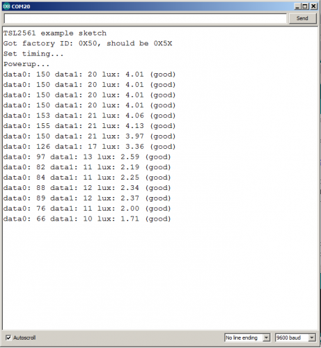
For CH0 and CH1 responses of 155 and 21, respectively, the chip calculates a value of 4.1, near the same value of 4.5 I get utilizing the equation.
Running the above script, I get similar CH0 and CH1 values of 177 and 22 and when input into the eqn above computes to be a value of 5.2, similar to that in the example; however,
far off the value of 75.1 reported on the screen monitor. As stated above, I used the identical sketch as above with a low gain setting of zero and an integration setting of 2 (402 ms) as indicated in the "Hookup Guide."
Again, I hope the format of this note is not a mess and conveys my dilemma.
