SparkFun Forums 

Where electronics enthusiasts find answers.

For the discussion of Arduino related topics.
By jeffpas
#163473
Hi All,

I have been on a quest to make a talking clock as a family gift for quite some time now, similar to the idea of the one sold here:
http://www.amazon.com/Message-In-Time-R ... B0006NHCW0

That is, a clock that plays a recorded message every hour. This I think was a great gift idea.
The problem is, the company that sells these went on the cheap, and now the clock they offer only plays the same message every hour, not 12 different ones like it originally did.

So I wondered if I could make my own. I ended up looking around online, and found a chip that can play recorded sound files if they are converted into the right format (the soundfile conversion I can do). I purchased a few parts after talking to an electronics store on recommendation, including an Arudino, and I'll list them here. The first part listed was what started me thinking it could be done. So now I have 4 parts altogether:

SoundOut audio module
http://www.embeddedadventures.com/sound ... -1007.html

Voltage power supply
http://www.embeddedadventures.com/level ... -1003.html

realtime Clock
http://www.embeddedadventures.com/real_ ... odule.html

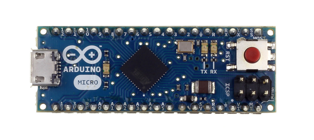
I also have an Arudino Micro "without headers".

The company I bought all this from claims it should be a rather simple thing, involving connecting them with some jumper wires and then I assume hooking up a speaker and power source, like a battery. They said the whole project should 'only take an hour or so'.

The problem is, its been over five weeks and they still have to get around to telling me how to connect the parts. The birthday I was making this for is already three weeks gone and I'm still left hanging.
Can anyone lend a hand with advice? I have basic electronics knowledge, my understanding is the sound files would be turned into .ad4 files, like 0000.ad4 0001.ad4 etc., put on the sound chip and then go. Some kind of language instruction would have to be put in (??) but I don't know where.
In any case I'm up to about $75 in parts, which is more than I expected. Could this have been done more cheaply? If I could just get some pointers I could probably complete this......... thanks for any help or advice.

jeffpas
By Mee_n_Mac
#163484
First : I see you've been bitten by the newbie 1'st post delay. Let's try to put all the answers in this thread. You may want to delete the other post (or point people to this one).

Second : what flavor of Arduino do have have ? 3.3V/8MHz or 5V/16MHz ?
https://www.sparkfun.com/products/10999
https://www.sparkfun.com/products/11098

Third : Divide and conquer. I assume this was to be battery powered ? Perhaps the first thing to do is figure out how to wire/power all the devices and then just get the sound card to play some files via manual control. Then you can get it to play via Arduino control. And then get the RTC working so it's plays on the hour(s). But we need to know the power source and the answer to #2 above.
By jeffpas
#163492
Hmmm.. nowhere on the box or board does it say voltage that I can see, which is strange. Just, Arduino Micro. There is an A000093, and what looks like 011 9U 94V-0 on the unit, but the 9U is in italics and smashed together.

Battery powered would be fine/great. The electronics store that was helping recommended the voltage converter, so I have to assume all 4 parts will work together. The voltage power supply says, "A regulator is also provided to give you up to 500mA of 3.3v power from 4-5v." So anything that will run the soundout card and clock (links above), I assume.

They mentioned a micro SD to USB adapter and jumper wires and I should be set. So connect them all together.... but how? I'm not sure what parts to connect to what parts with what wires, and obviously don't want to short anything out so experimentation is risky. As you can see they pretty much left me hanging in limbo :/ Thanks much
By Mee_n_Mac
#163496
So your first task is to find out which Arduino you have. It's the difference btw using/needing the regulator/translator board and not. Do you have a DVM ? If not it's worth the $15 to get one, even just for household use. You could power the Arduino up by plugging it into your PC's USB port and measuring the Vcc output on the pin/terminal labelled "Vcc". Something like the below is available at Home Depot or any hardware store or ... eeeek .. Radio Shack.
https://www.sparkfun.com/products/9141

Not knowing where your Arduino came from, I assume there's no silkscreen indication and marking like this:
Image

You should be able to examine the J1 solder jumper as well. The 5V version should have the 2 connections bridged with a blob of solder, like you see in the upper left corner here.
Image
Compare that to the open/unbridged version here. (same corner but now upper right in the pic)
Image

BTW what level of experience in programming the Arduino do you have ? While this task isn't hard, it's not starter level either. You'd also need to know which Arduino, 8 or 16 MHz, you have to get the Arduino IDE to talk to the Arduino.
By Mee_n_Mac
#163499
I just reread what you have for an Arduino and you might just have an official Micro, not one the SFE Pro Micros. If it looks like this :
Image
... then it's a 5V/16MHz board. That means you'll need the regulator/translator board after all. Too bad. I'll have to think about whether the 4 channels of translation (5V <-> 3.3V) is enough. I think so as the RTC board can run at 5V.
By jeffpas
#163501
Here is the Arduino I have:

http://store.arduino.cc/ww/index.php?ma ... cts_id=283

It says operating voltage, 5V. I happen to have a phone charger DC 5.0V wall plug that fits it perfectly. Is this safe then?
Would this then be the ultimate power source of the clock, that or connecting the micro usb end to a battery pack making 5 volts?
I am a programmer/computer support person, have done PHP, unix, Vbasic, Perl..... have never programmed in Ardunio but I don't expect it should be really difficult, I mean it would just look at the clock and kick off some sound files one every 60 minutes right? I'm just not quite comprehending how you would program it and of course how to connect the pieces together correctly.
By Mee_n_Mac
#163504
OK then, here's a markup of the Micro with the pins I think you'll used highlighted. Initially I would power it via the USB port as this keep it simple to start. Later on you could opt to keep that or use a wall wart power supply in the 7-12 V range (if you don't want to use the USB one you have now).
(click on to open)
ArduinoMicroFront.jpg
To get the sound board powered, you'll need to connect the 5V out pin above to the 5V pin on the regulator/translator board. You'll also need to connect one gnd pin from the Micro to a gnd pin on the regulator/translator (pick the one on the "5V side" of the board to make things look simple.

Then you'll need to connect the 3.3V out from the regulator/translator board to the Vcc input pin of the sound board. You'll also need to connect the other gnd pin (on the "3.3V side") of the regulator/translator board to the gnd pin of the sound board. Find a speaker (almost any will do) and wire it's 2 terminals to the spk terminals of the sound board. There is no polarity for this connection, any speaker terminal to any spk pin is OK.

At this point when you plug the USB power to the Micro, it should power the regulator/translator board and that, in turn, the sound board. You can try to make it play the included files by just using a wire to temporarily connect the PLAY pin to the the sound board GND. You can advance the track or go back by tapping that gnd wire to either the NXT or PRV pins. Don't be surprised if you skip several tracks given the shaky nature of your "switch". Actually perhaps the 1'st thing to do after a power up is a temporary reset, touch the ground wire to the RST pin.

If you can get it to make sounds then the next thing to do is put the sound files you want on the SD card and verify them via the above process. That process is described in the manual below and you can read it as well as I. I can't add anything that's not there.
http://www.embeddedadventures.com/datas ... _hw_v4.pdf
You do not have the required permissions to view the files attached to this post.
By Mee_n_Mac
#163519
Here's a 1'st cut at a schematic showing all the connections you'll need (and maybe even more than you need). In short the RTC get's it's power from the 5V regulator on the Micro. It talks to the Micro via an I2C bus and so uses the Micro's D2 and D3 pins for the I2C data (SDA) and clock (SCL) lines. There's also an interrupt from the RTC that you might use and so I've routed that to D7 (long story here for later).
http://en.wikipedia.org/wiki/I%C2%B2C

The sound board is a 3.3V device and so gets it's power from the regulator/translator board. Since that's already been discussed above, enough said. There are 3 needed and 1 extra signal to go between the Micro and sound card. These have to go through the level translator so the 5V signals don't blow out the 3.3V sound board pins. These are a reset signal, a data signal and a clock signal from the Micro. Since you had a spare channel left over, I also brought the busy signal from the sound board to the Micro. Might be useful, maybe not. The speaker gets connected as previously mentioned.

For the moment I've assumed the system power will come in from the USB connector. That's easily changed if needed/desired.

Since I'm lazy and didn't want to draw blocks for the components, I just copied and pasted their PCB images and so the "schematic" is almost more like those Fritzing wiring diagrams I hate. While I'm not a fan of a lot of color on a schematic, I thought it might help you follow the signals so here it is.
(click on to open an enlarge)
TalkingClockSchematic_rev0.jpg
You do not have the required permissions to view the files attached to this post.
By Mee_n_Mac
#163527
BTW the above was one possible way to wire it all. Obviously other GPIO pins could have been used to talk to the sound card. Indeed if you look at the PDF file for it, they mention using the I2C port to send messages to the sound card. I opted not to do this for a few reasons. First my belief is that the RTC needs the I2C in a more standard usage, the sound card isn't really I2C but just uses the port resources. This would mean reconfiguring the port btw RTC and sound card messaging. That bothered me. Second the sound card message format is simple, simple enough it could be bit banged (if the Arduino ShiftOut can't be used) so this approach seemed more straight forward than swapping I2C configurations. Lastly it would have meant running the RTC off the 3.3V supply as well and sending the SDA and SCL lines through the translator. I don't know how well that will work. It should, it's just another (perhaps trivial) difference from a standard configuration. Sometimes getting the pull-up resistors right can be a PITA w/multiple devices on the lines, let alone a translator. KISS.

So I opted to keep the RTC on the 5V supply and use the real SDA, SCL pins to talk to it in a real I2C manner. Then use some GPIO pins to talk to the sound card. From the PDF :

To reset the device, hold the RST pin low for at least 5ms. Then, wait 300ms for the
module to read the SD card, calculate the phase of the moon, and prepare for
playback.

At the start of each command, pull the CLK line low for 2ms, then clock in the 16 bit
command, most significant bit (MSB) first. For each bit, change the data line while
the CLK line is low, then pulse the CLK line high to load the bit into the MOD-1007.
Each CLK pulse should be at least 50μS long.

It is not necessary to reset the device every time you want to send a command. It’s
a good idea to do it the first time you start communicating with the module though.
BSY will be high while playback is occurring and low otherwise. You can tell when a
file has finished playing back by waiting for the BSY line to return low.

Commands are 16 bit words.
0x0000 => Starts playback of 0000.ad4
...
0x01FF => Starts playback of 0511.ad4
0xFFFx => Sets volume: 0xfff0 mute to 0xfff7 loud (default)
0xFFFE => Play (or pause if already playing)
0xFFFF => Stop playback

So to playback 0000.ad4, send 0x0000. To start playback of 0001.ad4, send
0x0001 and so on. You can send volume commands whether playback is occurring
or not.


Looked pretty simple to me. A timing diagram is shown in the PDF.
http://www.embeddedadventures.com/datas ... _hw_v4.pdf
By jeffpas
#163587
first, Mee_n_Mac, thanks for all your help. And I might go this way but -
2nd, jremington: I'm not sure I understand, but are you saying I could do this with just 4 things:

An arduino Uno
A temporary switch
A speaker
A DS1307 clock

I have an ardunio, I assume the one I have would not work? What about the clock unit I purchased?
Ardunio
http://store.arduino.cc/ww/index.php?ma ... cts_id=283
Clock
http://www.embeddedadventures.com/real_ ... odule.html

What is a 'temporary switch'?

This appears it might be a simpler way to go, but not sure. All I want is to be able to create 12 or 24 sound files on say a micro SD, and then instruct the unit to play the sound files one at the top of each hour to the speaker.
The simplest way I can do this the better. I have no idea if the company I bought these parts from had me get more than I needed, but right now its looking around $75 just for the innards (not even the clock case, etc) which I just feel is pretty steep especially if I ever wanted to make another one. The talking clock originally being sold on Amazon was only $45, and it was of course completely finished (though no longer available :/ )
I suppose there would have to be a way to 'set' and 'see' the time of course, though the time doesn't necessarily have to be displayed.

??
thanks!
By jremington
#163588
A temporary switch is a pushbutton switch. The real time clock module that you have could be substituted for the DS1307, and any 16 MHz arduino would work. Download and study the examples in the "talkie" link to see how easy it is to say words and create phrases. You would not need anything other than the arduino and a speaker or headphones to test the examples and of course, a PC to program the arduino.

You have to add code to set and use the RTC. On the other hand there is lots of arduino code available to create a software clock, e.g. http://playground.arduino.cc/Code/DateTime The disadvantage of a software clock is that it would be less accurate than the RTC and unlike a battery-backed RTC, would need to be reset every time the power was cycled. You would need to check for a possible conflict with timer usage, as the speech routines use TIMER1 and TIMER2 (the delay() and millis() functions use TIMER0).
Last edited by jremington on Tue Sep 17, 2013 12:16 pm, edited 1 time in total.
By Mee_n_Mac
#163601
I would add that using the speech tech in the "talkie" is a bit less natural sounding than a true human voice. Also the sounds to be played back are stored in the flash memory in the Arduino ... which is more limited that that of an SD card. But if the tonality sounds good enough and the length and sound of the clips to be played are good enough to fit in flash ... then you could forgoe the translator/regulator board and the sound board ... about 50% of your cost ?? Then again you'll need a piezo speaker to be driven directly from the Arduino pins.

As said above you can experiment and find out what's good enough for you. Remember the KISS principle.
By jeffpas
#164885
guys, very late getting back to this-
much appreciate these detailed diagrams and assistance you provided. This is just what I was looking for.
I have everything wired up as shown and the sound files created, 12 of them one for each hour of the day (at least for now... probably it will be silent from 1am to 7am)
I tested the wiring and hooked it up to a speaker, and its working. Which is pretty cool :)
I then wired everything up with the clock module.
I also downloaded the pic pack library and I have two files, ms5611.c and ms5611.h and put them on the SD card.
I have a little bit of C programming experience.....so I'm sure once I can understand the gist of what is going on here I can get it to work.

But what I'm trying to understand is.... I assume then an executable 'driver' file and perhaps library files are placed on the SD card along with the .ad4 sound files, and they then kick off when the card is plugged in to the 5V adapter via the mini-USB? I thinking the code here is part:
http://playground.arduino.cc/Code/DateTime

I'm also trying to comprehend here how the unit would then be set so that the time is accurate, and then I assume a program loop would kick off each sound file in sequence, one every 60 minutes. But whoever I give this clock to, they are going to want to know how to set the clock time relatively easily to the right time, especially if they unplug it and move it to another room.

Also it appears the clock module has a mini battery built in.... I'm wondering if then it would retain the current time even if unplugged from the wall? However when that battery dies it would still have to be set again........ anybody have any thoughts? This is all entirely new... first time I have ever worked with boards. thanks!
By Mee_n_Mac
#164910
jeffpas wrote:I also downloaded the pic pack library and I have two files, ms5611.c and ms5611.h and put them on the SD card. I have a little bit of C programming experience.....so I'm sure once I can understand the gist of what is going on here I can get it to work.

But what I'm trying to understand is.... I assume then an executable 'driver' file and perhaps library files are placed on the SD card along with the .ad4 sound files, and they then kick off when the card is plugged in to the 5V adapter via the mini-USB? I thinking the code here is part:
http://playground.arduino.cc/Code/DateTime
Errrrr I believe the files ms5611.c and ms5611.h are the source files you're supposed to compile and whose subsequent binary gets loaded into the flash memory of the Arduino. Since those files were for PICs, not "Arduinos", I'd expect to have to redo some of the C source code.

Only the sound files go on the SD card, per the manual.

The Arduino is like a CPU w/memory. There's no OS to handle files or kick off events. The bootloader on the Arduino only knows how to D/L new code (if there's a PC connected) or run the code stored in flash.
jeffpas wrote:I'm also trying to comprehend here how the unit would then be set so that the time is accurate, and then I assume a program loop would kick off each sound file in sequence, one every 60 minutes. But whoever I give this clock to, they are going to want to know how to set the clock time relatively easily to the right time, especially if they unplug it and move it to another room.

Also it appears the clock module has a mini battery built in.... I'm wondering if then it would retain the current time even if unplugged from the wall? However when that battery dies it would still have to be set again........ anybody have any thoughts? This is all entirely new... first time I have ever worked with boards. thanks!
You are correct re: the battery. I will GUESS that the "ms5611" code running on the Arduino allows some way, via the keyboard->PC->USB->Arduino->RTC to set the time. If this doesn't work for the end user, you'll need to write some code to somehow set the date/time via some new buttons tied into the Arduino ... like how you set a normal clock.