- Fri Jan 07, 2011 6:28 am
#116815
Hi all. I used an Arduino for my project. Wanting to use my Arduino further, I designed and had a PCB made with the ATmega, crystal, caps, etc needed to run the Arduino, as well as everything else for my project. It worked 100% in the breadboard, but now that it's assembled on the PCB I'm having issues.
Basically when the computer is turned on, 12v and 5v goes into the board. The arduino uses the 5v as a sense to know when the computer is on. The 12v then runs into a 5v regulator, and out to a pair of 5v 10F caps in series. The Arduino takes a reading from a temp sensor, and runs a servo accordingly. When the computer is shut off, the 10F caps provide power to set the servo to its closed position (the Arduino does the when the 5v is taken away from the sense pin = computer off).
The problem I'm having is that on first startup when the caps are drained, it doesn't do anything. You can freely move the servo by hand. Now if I unplug and plug it back in a couple times it'll work fine. It works as long as there's a small charge in the caps. If I let them drain completely, it won't work again. Now this worked 100% in the breadboard setup, but for some reason doesn't want to work now lol. Any ideas? Am I missing something? I designed the PCB directly from the breadboard setup.
Link to original design thread:
http://www.thebestcasescenario.com/foru ... 932&page=3
Link to project this is used in:
http://www.thebestcasescenario.com/foru ... post289709
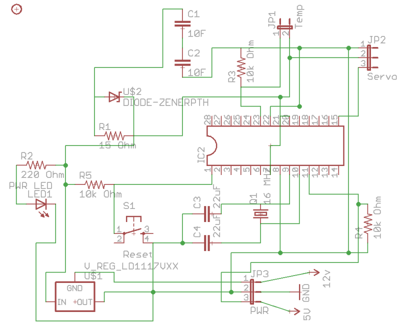
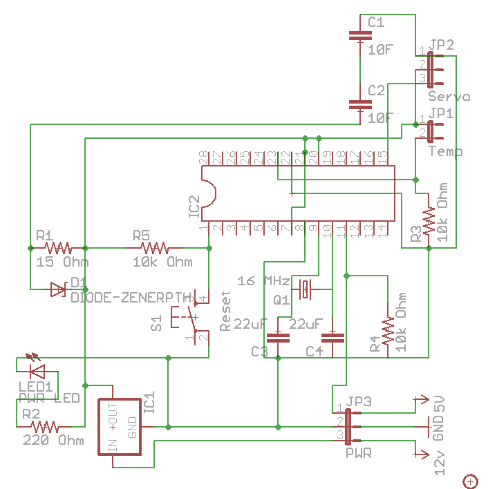
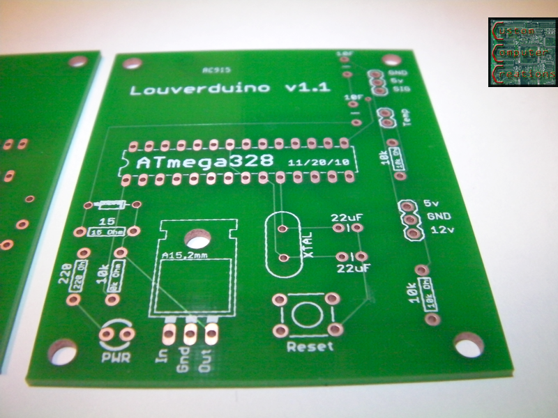
the Eagle layout:
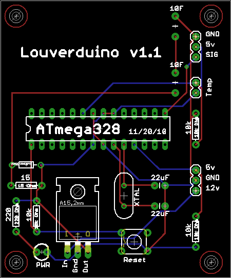
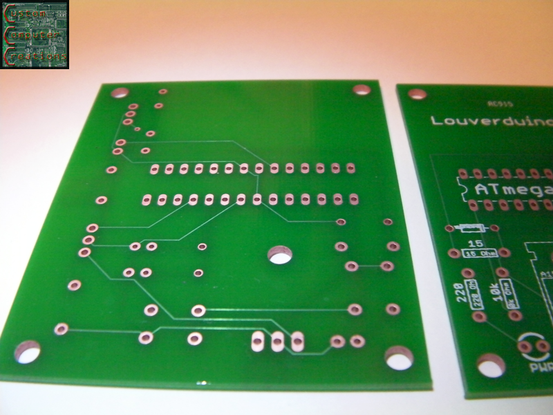
The boards:
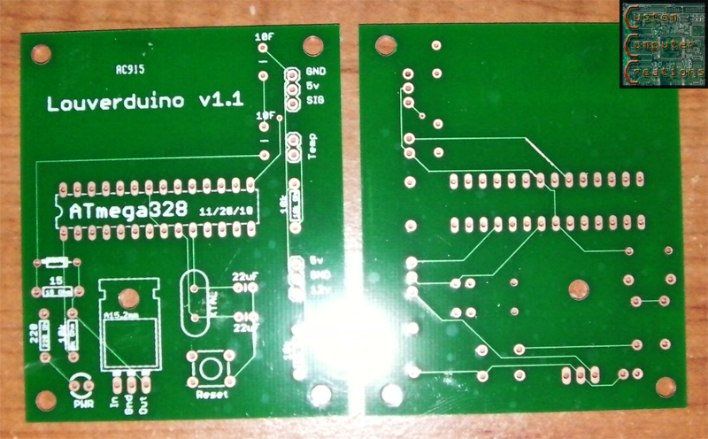
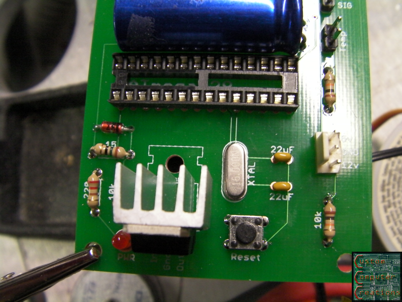
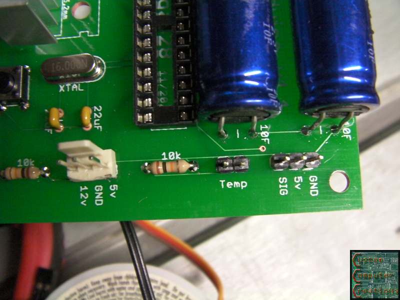
Assembled:
Basically when the computer is turned on, 12v and 5v goes into the board. The arduino uses the 5v as a sense to know when the computer is on. The 12v then runs into a 5v regulator, and out to a pair of 5v 10F caps in series. The Arduino takes a reading from a temp sensor, and runs a servo accordingly. When the computer is shut off, the 10F caps provide power to set the servo to its closed position (the Arduino does the when the 5v is taken away from the sense pin = computer off).
The problem I'm having is that on first startup when the caps are drained, it doesn't do anything. You can freely move the servo by hand. Now if I unplug and plug it back in a couple times it'll work fine. It works as long as there's a small charge in the caps. If I let them drain completely, it won't work again. Now this worked 100% in the breadboard setup, but for some reason doesn't want to work now lol. Any ideas? Am I missing something? I designed the PCB directly from the breadboard setup.
Link to original design thread:
http://www.thebestcasescenario.com/foru ... 932&page=3
Link to project this is used in:
http://www.thebestcasescenario.com/foru ... post289709
the Eagle layout:
The boards:
Assembled: