- Mon Nov 01, 2010 8:53 am
#112541
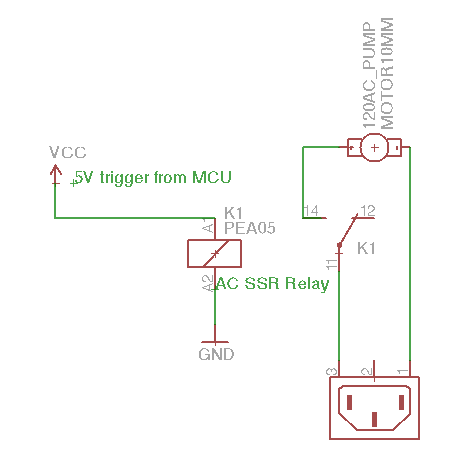
I built a basic relay circuit using an AC solid state relay to turn on an AC pump. Send 5v into the SSR and the pump turns on.
I also built a basic button controlled PWM circuit using my arduino. For each button tap it increases the PWM duty by 10%. I connected LED's to test and as expected the LED's gradually increase in brightness with each press.
I then connected the PWM output on the arduino to the 5v trigger on the SSR expecting it to control the pump speed but nothing happened. I can turn the output to HIGH and the pump will turn full on, and the SSR is rated to as low as as 3v input trigger but still nothing happens no matter what speed the output is set at.
I could really use some suggestions as what to try to fix this and make it work. Thanks!
www.pcmofo.com