- Sun Aug 13, 2017 12:18 am
#195829
Hi everyone,
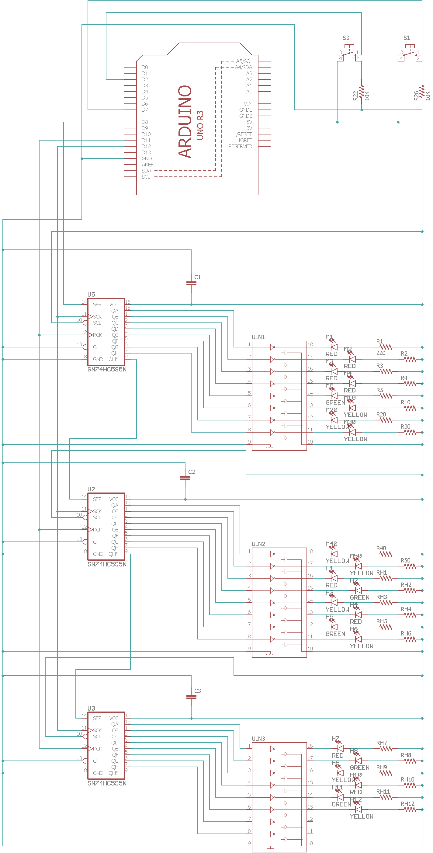
I'm designing an LED clock using an Arduino, 74HC595s for the control, and ULN2803s for grounding the LEDs.
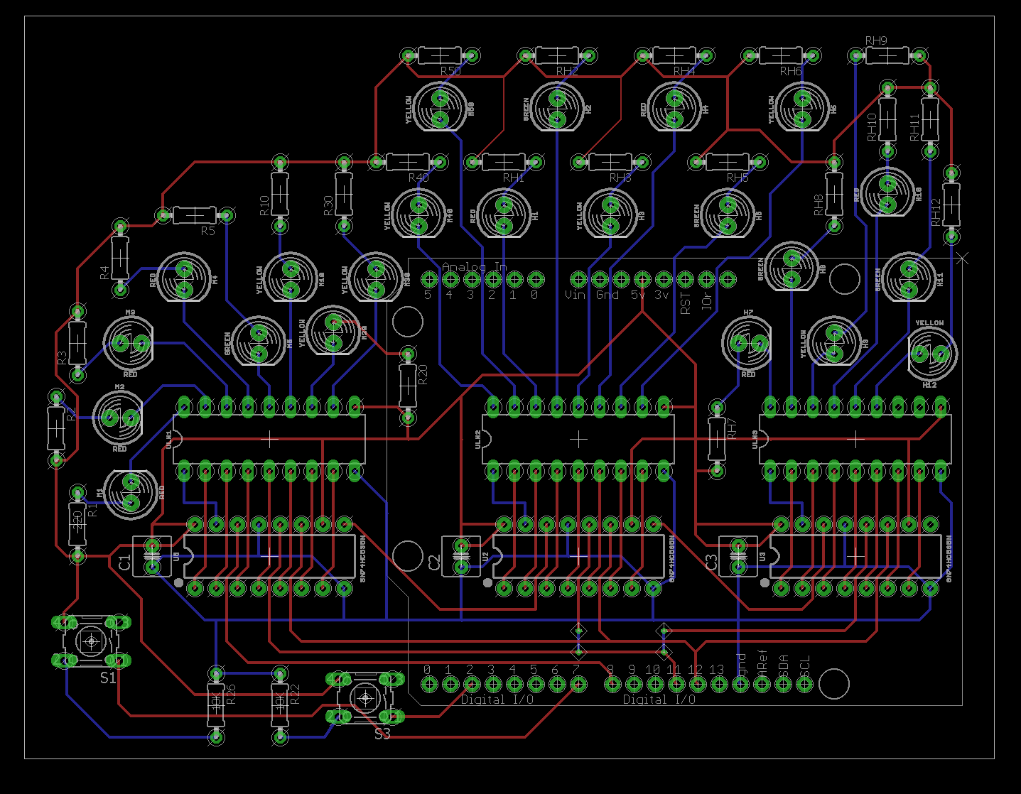
I've got everything working on a breadboard, designed on a schematic and a first version laid out on a pcb in Eagle. I've never designed a pcb before, so I'm sure there's lots of little errors.
The main question I have is related to decoupling capacitors and a ground plane. I was having trouble finding out online if the capacitors should have their own pathway to the 74HC595s, or if they could both simply be connected to the ground plane.
I haven't put the ground plane in in this version, and any suggestions overall are much appreciated.
Thanks for any help
Schematic: http://ffsmultimedia.com/eagle/clock-sch-v1.png
PCB: http://ffsmultimedia.com/eagle/clock-brd-v1.png
I'm designing an LED clock using an Arduino, 74HC595s for the control, and ULN2803s for grounding the LEDs.
I've got everything working on a breadboard, designed on a schematic and a first version laid out on a pcb in Eagle. I've never designed a pcb before, so I'm sure there's lots of little errors.
The main question I have is related to decoupling capacitors and a ground plane. I was having trouble finding out online if the capacitors should have their own pathway to the 74HC595s, or if they could both simply be connected to the ground plane.
I haven't put the ground plane in in this version, and any suggestions overall are much appreciated.
Thanks for any help
Schematic: http://ffsmultimedia.com/eagle/clock-sch-v1.png
PCB: http://ffsmultimedia.com/eagle/clock-brd-v1.png