- Tue Oct 22, 2013 5:30 pm
#164757
First the why, then the question...
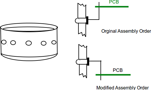
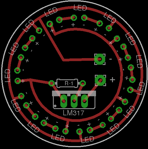
Have a project underway that may get scaled up to a small production situation in tbe near future. I requires 15, 5mm LEDs mounted radially (inserted from the inside) in a small diameter cylinder (1.5" pvc pipe cap). The unit will be potted after connections are complete. Breadboarded the circuit and it is undergoing stress testing. Next step was to figure out how to actually wire it inside the small available space. As a "rats-nest" is out of the question I figured a PCB was a good start. After a couple of days of teaching myself enough Eagle to be dangerous, I came up with a simple single-side round board I could proto at home or get a couple cheap copies made.
Doable, but after inserting all the LEDs in the housing (leads bent 90deg vertical) I would still have to thread the board down over 30 leads at the same time before soldering.
Came up with the idea that if I could slot the edge of the board, providing an 0.032 slot (same size as the drill for a std 5mm LED package) as below, it would allow me to work the board one lead at a time rather than trying to thread 30 at once.

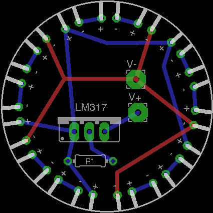
Of course I would have to go to a 2 sided board, something like this.
Now the question... How would you go about slotting the board? From what I have read, the tooling used for milling out an odd shaped board is well in excess of 0.032" in diameter so I shouldn't expect a fab house to be able to just follow the outline as drawn, without wallowing out the through-holes and pads. I thought this would be an innovative solution to the assembly problem, but am stuck on how to accomplish it. Best solution would be one the fab house could handle, but an after fabrication/before assembly modification would be all right as well. Very little experience in PCB fabrication and modification, so any suggestions are very much appreciated.
Thanks for your interest.
Have a project underway that may get scaled up to a small production situation in tbe near future. I requires 15, 5mm LEDs mounted radially (inserted from the inside) in a small diameter cylinder (1.5" pvc pipe cap). The unit will be potted after connections are complete. Breadboarded the circuit and it is undergoing stress testing. Next step was to figure out how to actually wire it inside the small available space. As a "rats-nest" is out of the question I figured a PCB was a good start. After a couple of days of teaching myself enough Eagle to be dangerous, I came up with a simple single-side round board I could proto at home or get a couple cheap copies made.
Doable, but after inserting all the LEDs in the housing (leads bent 90deg vertical) I would still have to thread the board down over 30 leads at the same time before soldering.
Came up with the idea that if I could slot the edge of the board, providing an 0.032 slot (same size as the drill for a std 5mm LED package) as below, it would allow me to work the board one lead at a time rather than trying to thread 30 at once.
Of course I would have to go to a 2 sided board, something like this.
Now the question... How would you go about slotting the board? From what I have read, the tooling used for milling out an odd shaped board is well in excess of 0.032" in diameter so I shouldn't expect a fab house to be able to just follow the outline as drawn, without wallowing out the through-holes and pads. I thought this would be an innovative solution to the assembly problem, but am stuck on how to accomplish it. Best solution would be one the fab house could handle, but an after fabrication/before assembly modification would be all right as well. Very little experience in PCB fabrication and modification, so any suggestions are very much appreciated.
Thanks for your interest.
Last edited by capcouillon on Sun Oct 27, 2013 2:48 pm, edited 1 time in total.