Tips on a protection pcb for the OS4000 compass module
Posted: Tue Feb 28, 2012 7:48 pm
So we got the nice, expensive, (now retired) OS4000.
http://www.sparkfun.com/products/8960
I was wondering if you guys had any tips or tricks to improve on the schematic I've come up with for protection:
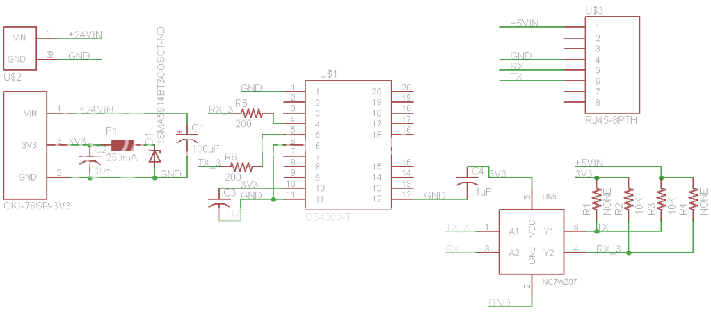
if the image doesn't show up in its entirety:
http://i480.photobucket.com/albums/rr17 ... ematic.png
Misc parts:
-Open-drain buffer:
http://search.digikey.com/us/en/product ... -ND/965702
-OKI-78SR
http://parts.digikey.com/1/parts/186750 ... w36-c.html
-F1: a 250mA PTC
-D1: 3.6V Zener Diode, 1W
The RJ45 connector is connected to a 5V TTL level UART off of an ARM board. +5Vin is supplied by the ARM board, but really can't supply much current.
So, does anyone feel like tearing this thing to pieces? :doh:
What I'm designing against is the possibility of 24V being applied to any of the pins on the RJ45 connector, in addition to ESD at any of the connectors...
http://www.sparkfun.com/products/8960
I was wondering if you guys had any tips or tricks to improve on the schematic I've come up with for protection:
if the image doesn't show up in its entirety:
http://i480.photobucket.com/albums/rr17 ... ematic.png
Misc parts:
-Open-drain buffer:
http://search.digikey.com/us/en/product ... -ND/965702
-OKI-78SR
http://parts.digikey.com/1/parts/186750 ... w36-c.html
-F1: a 250mA PTC
-D1: 3.6V Zener Diode, 1W
The RJ45 connector is connected to a 5V TTL level UART off of an ARM board. +5Vin is supplied by the ARM board, but really can't supply much current.
So, does anyone feel like tearing this thing to pieces? :doh:
What I'm designing against is the possibility of 24V being applied to any of the pins on the RJ45 connector, in addition to ESD at any of the connectors...