SparkFun Forums 

Where electronics enthusiasts find answers.

General suggestions or questions about the SparkFun Electronics website
By busonerd
#42471
Well, in our tests we didn't set it up to regulate for voltage as it is normally. The switcher basically had the comparator pin connected to a current sense resistor on the negative side of the backlight. You need to watch out for runaway with that configuration though - if you disconnect the backlight, the switcher will be on @ 100% duty cycle. A solution to that is to add a voltage trip as well. I never got around to implementing it, but IIRC I was planning to use a 25V zener to force the comparator pin > 1.25V, so the switcher would stop @ 26V.

Cheers,

--David Carne
By apullin
#43730
Was the Verilog code ever released? I can't seem to find it via a search, but I could just be a fool. I'd be very interested in it, if it was available...

Thanks,
Andrew
By busonerd
#43740
Hey,

Email someone @ sparkfun for it - I don't have a copy of it around anymore. It was never really polished enough to release.

Cheers,

--David Carne
By b_bogk77
#43745
Is SF still planning to release a FPGA to PSP lcd adaptor?
By pellepl
#48345
Did anyone ever finish off a working pcb with the s1d13742 driver chip? I thought I just did, but I seem to have done some bad pcb design choices - the PLL refuses to lock on to my 8Mhz oscillator. :( Is there anyone out there understanding this oscillating/PLL business?
By oracleguy
#48639
busonerd wrote:Well, in our tests we didn't set it up to regulate for voltage as it is normally. The switcher basically had the comparator pin connected to a current sense resistor on the negative side of the backlight. You need to watch out for runaway with that configuration though - if you disconnect the backlight, the switcher will be on @ 100% duty cycle. A solution to that is to add a voltage trip as well. I never got around to implementing it, but IIRC I was planning to use a 25V zener to force the comparator pin > 1.25V, so the switcher would stop @ 26V.

Cheers,

--David Carne
Just so the information is out there:

I tried to build that circuit but it ended up being too touchy and didn't fit my design well.

What I ended up doing is using a DC-DC converter (which was a very small package), specifically a NME0524SC which is a SIP version, the DIP version is NME0524DC. Then I just put a 1.5k ohm resistor in series with the backlight to limit the current and it has been working great.

To drive the screen I was able to use an Epson S1D13743 successfully.
By pellepl
#48646
That's good news! Would you care to enlighten a poor soul like myself, I'll put a picture of you on a piedestal by my desk ;) I keep banging my head on this, close to coming to a nervous breakdown.

Did you make your own PCB - if so, I presume you used the QFP package? Did you utilize the PLL, and if so, did you make use of all the guidelines concerning PLL power supply? Also, what oscillator did you use?

Basically, I'd like to see your design (and probably steal it right off), but where's the sport in that? ;)
By oracleguy
#48649
pellepl wrote:That's good news! Would you care to enlighten a poor soul like myself, I'll put a picture of you on a piedestal by my desk ;) I keep banging my head on this, close to coming to a nervous breakdown.

Did you make your own PCB - if so, I presume you used the QFP package? Did you utilize the PLL, and if so, did you make use of all the guidelines concerning PLL power supply? Also, what oscillator did you use?

Basically, I'd like to see your design (and probably steal it right off), but where's the sport in that? ;)
Lol. I know how you feel. My team and I spent a ton of time getting it to work. And since it was such a pain and there isn't a lot of clear information, I am happy to share.

I used the QFP package, the board I built I wirewrapped. I used an adapter to convert the QFP package into something wirewrappable. But that doesn't really effect the operation of the design.

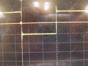
I used a 1MHz square wave input (from a can oscillator) and then using the PLL I upscaled it to 45MHz internally and then divided that down by 5 to generate the 9MHz PCLK required by the screen.

As for the power supply guidelines, I tried to get some more information out of some FAEs at Epson without too much luck. But basically I ended up not using it. However my power supply rails only had 50-90mV variances. But the data sheet makes it sound mega dangerous to have any variance.

Also it is critically important to put the device into sleep mode before you configure the PLL registers otherwise it won't work. There is a register to control the sleep mode.

I used a PIC18 microcontroller to run my system and it talked to the Epson chip.

I am planning to write up how exactly my team and I did it and I can even provide a register dump of the Epson chip. And some things we learned about the screen in the process. I'm hoping to write it up this weekend, when I do I'll post back.
By pellepl
#48659
Ah, wirewrap - were you using decoupling caps then? If you didn't I guess epson greatly exagerrate the need for stable power.

I do enable the sleepmode, but still no lock. Having supplies with ~50mV variance, so it shouldn't be that. Perhaps the oscillator; did you put in any resistance in series with the clock input?

Anyhow, really looking forward to a success story - don't let it spoil the weekend though ;)

Thanks for giving hope! :D
By oracleguy
#48662
I was using decoupling capacitors. However as for getting a lock, the biggest problem with that is if you have a bad clock signal. At first I was using a function generator and it wouldn't lock with it due to too much noise on the edges. Once I gave it a better clock signal the PLL would lock.

Take a look at your clock signal input and see how clean it is. If it has issues that will prevent a lock. Also there is a certain point in the startup where you need to wait for a lock or up to 10ms before continuing. I believe it is mentioned in the sample startup procedure in the datasheet.
By pellepl
#48666
Here's the story: getting desperate, I decided to sacrifice my PCB. I cut the clock trace to the oscillator with a pen knife and connected a PWM signal from my uc directly to the CLKI pin.

Guess what - *drumroll* - the PLL locked on real nice!

Darn, the specs on the oscillator are well within limits! And looking at the oscillator signal gives no hint, it's square enough by the view of it..! Perhaps my 8MHz are flattened out along the trace, but still - the trace is only 0.2 inch long and 10 mils wide.

I guess the lesson learned is that high frequency is evil, or rather that PLLs are fretful beasts.

Gazillions of thanks for hinting me in the right direction! You've saved me a lot of frustration! Send me a piccie and I'll print it out ;)
By oracleguy
#48668
I'm glad to hear it!

I should of posted this last time but I do have pictures of my bad clock signal and then my good one. The bad one wouldn't lock.

Bad:
Image

Good:
Image

Mind sharing what you are building? (You can send me a PM if you want)
By pellepl
#48671
My squares were a lot less square than yours when it worked - by working I mean getting PLL lock, havent went further to actually connect the display. My clock was more roundish at transitions.

I'll gladly post my stuff when (if) I finish this off, have to do some more soldering and find me a new oscillator. Oh, and get some sleep also.

Planning to redesign my PCB to give possibility for external clock instead of only on-card. My pen-knife went a bit dull so it would be a good feature I reckon..
By PSPMAN90
#49449
How to install This PSP Touch Screen to a PSP? Sorry 4 the noobish question, but thi is for the PSP rigth? Can someone tell me how do U install this on a PSP? Thanks!
By seulater
#54030
Well, what do ya know, those questions we had about using this S1D13742 for the PSP screen and the 5 bits...
well I just went back to their site and they got this handy dandy pdf named "Interfacing the Sharp LQ043xxx 480x272 TFT Panel "
How awesome is that!!!!
here is the link for it.
http://vdc.epson.com/index.php?option=c ... &Itemid=99

now I am all fired up to make this board and try it.