SparkFun Forums 

Where electronics enthusiasts find answers.

Have questions about a SparkFun product or board? This is the place to be.
By oPossum
#42509
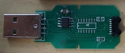
New simplified circuit...

Image

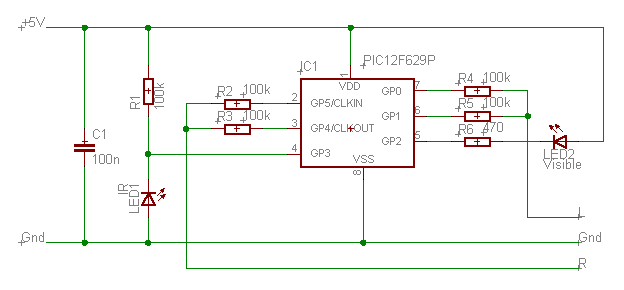
The 74HC logic has been replaced with a PIC 12F629.

A reverse biased IR LED is used as an IR detector. This requires good alignment with the remote, so a visible LED provides feeback.

The 'DAC' no longer has DC blocking caps or a voltage divider. It is assumed that the sound card is AC coupled and has an input impedance of about 10k.

The PIC code is very simple...
Code: Select all
	include <P12F629.INC>
	#define PGMSIZE 1024

    __config _CPD_OFF & _CP_OFF & _BODEN_ON & _MCLRE_OFF & _PWRTE_ON & _WDT_OFF & _INTRC_OSC_NOCLKOUT


                                                    ; --- I/O
                                                    ; 8 Ground
bLeft1          equ 0                               ; 7 Left 1
bLeft2          equ 1                               ; 6 Left 2
bStatusLED      equ 2                               ; 5 Status LED
bIRLED          equ 3                               ; 4 IR LED (used as IR detector)
bRight2         equ 4                               ; 3 Right 2
bRight1         equ 5                               ; 2 Right 1
                                                    ; 1 Power
                                                    ;
                                                    ;
                                                    ;
    org     0x0000                                  ; - Start of program memory

                                                    ; - Initiailize peripherals
                                                    ;
    movlw   (1<<CM0) | (1<<CM1) | (1<<CM2)          ; Disable comparator
    movwf   CMCON                                   ;
                                                    ;
    call    PGMSIZE-1                               ; Get OSCCAL
                                                    ;
    bsf     STATUS,RP0                              ; Bank 1
                                                    ;
    movwf   OSCCAL ^ BANK1                          ; Setup OSCCAL
                                                    ;
#ifdef ANSEL                                        ;
    movlw   (1<<ADCS0) | (1<<ADCS2)                 ; Disable ADC, make all pins digital I/O
    movwf   ANSEL ^ BANK1                           ;
#endif                                              ;
                                                    ;
    movlw   (1<<bIRLED)                             ; Setup TRIS
    movwf   TRISIO ^ BANK1                          ;
                                                    ;
    bcf     STATUS,RP0                              ; Bank 0
                                                    ;
                                                    ;
loop                                                ;
    movlw   (1<<bRight1)|(1<<bLeft1)|(1<<bStatusLED); Neutral output, Status LED off
    movwf   GPIO                                    ;
                                                    ;
    btfsc   GPIO,bIRLED                             ; Wait for IR on
    goto    $-1                                     ;
                                                    ;
    movlw   (1<<bLeft1)|(1<<bLeft2)                 ; Left High, Right Low output, Status LED on
    movwf   GPIO                                    ;
                                                    ;
    btfss   GPIO,bIRLED                             ; Wait for IR off
    goto    $-1                                     ;
                                                    ;
    movlw   (1<<bRight1)|(1<<bLeft1)|(1<<bStatusLED); Neutral output, Status LED off
    movwf   GPIO                                    ;
                                                    ;
    btfsc   GPIO,bIRLED                             ; Wait for IR on
    goto    $-1                                     ;
                                                    ;
    movlw   (1<<bRight1)|(1<<bRight2)               ; Left Low, Right High output, Status LED on
    movwf   GPIO                                    ;
                                                    ;
    btfss   GPIO,bIRLED                             ; Wait for IR off
    goto    $-1                                     ;
                                                    ;
    goto    loop                                    ;
                                                    ;
                                                    ;
    end                                             ;
                                                    ;
By Jaynix
#45089
Hi oPossum,

Thanks for your schematics and explanations.
I'm an experienced electrical engineer, though i've got a very little knowledge in Infrared stuff.
I'd like to use this kind of technique to control a TV (just to turn it on/off with my computer).

So i made the very same circuit (the one with the 74HC..), but it doesn't work as expected on a Macbook Pro.

I can capture the IR signal.
But when played back on the IR beamer (two IR LEDs linked in // and opposite on L and R channel with a 20 ohms resistor in serial).

I've checked/compared the output signal on the circuit and on the IR Beamer with an oscilloscope and they are similar.
The LEDs are lighting up and blink pretty much, so it's not related to low power from the audio output.

On the picture there is no preamble (500Hz Sine or Square).
Even if i put it, it is the same result.
Does it really need the preamble signal ?

Image

When you say it works for you, do you mean you can record a command from any remote control and play it back with the IR Beamer to control the remote's device ?
By oPossum
#45098
It looks like you may have used an IR demodulator rather than a QSE156 IR detector. I don't see any carrier in the recording.

I only tested it with one buttton on one remote. It should work for anything with a 30 to 40 kHz carrier.
By Jaynix
#45101
I found the problem.

When i play back the captured signal, this what i get.

Image

Orange = Circuit audio out left (R5/C1).
Blue = Computer audio out left (IR LEDs / Ground) playing the captured signal.
Purple = pin out of the QSE156 when it detects the signal from the IR LEDs.

As you can see the signal is not correctly received by the QSE.
I tried to replace the IR LEDs of the beamer, suspecting them but it is still the same.

I start to believe the built-in sound card of the MacBook Pro is responsible of this.

Any idea ?
Last edited by Jaynix on Fri Mar 21, 2008 3:10 am, edited 1 time in total.
By Jaynix
#45102
oPossum wrote:It looks like you may have used an IR demodulator rather than a QSE156 IR detector. I don't see any carrier in the recording.

I only tested it with one buttton on one remote. It should work for anything with a 30 to 40 kHz carrier.
I think you are right, this is why it is not working.
The electronic shop sold me this piece claiming it was the same when i asked why there is no references on it. :/

Can you suggest me other references that will do the job ?
Can i use the one inside my USB IRDA dongle ?
By oPossum
#45106
Jaynix wrote:I think you are right, this is why it is not working.
The electronic shop sold me this piece claiming it was the same when i asked why there is no references on it. :/
It's not. They sold you an ordinary IR demod module.
Can you suggest me other references that will do the job ?
A reverse biased IR LED (like the PIC circuit above) and a 74HC14 buffer would probably work.
Can i use the one inside my USB IRDA dongle ?
Yes! I have done this with my IR Widget. (bottom of page) There is usually a cap in parallel with the IRDA module power pins. Easy to find the IR out pin with a 'scope.
By oPossum
#45107
Jaynix wrote:I start to believe the built-in sound card of the MacBook Pro is responsible of this.
Nothing wrong with the MBP - just low frequency rolloff.

What software did you use for audio recording on the Mac? I don't recognize it.
By Jaynix
#45108
I used SoundStudio for the capture, but i also use Audacity.

Thanks again for your help. :)

edit. oups i haven't seen your answer :D

My irda dongle is this one (with the well-known non standard WD969 chip from Kingsun).

Image
By Jaynix
#45110
Opossum you're the guy !

It works !!! :D