SparkFun Forums 

Where electronics enthusiasts find answers.

Have questions about a SparkFun product or board? This is the place to be.
By GTBecker
#47217
automata wrote: ... the Edmund Scientific photo diode operating at 35 MHz might work for a highspeed photodetector.
Well, I tested the 15MHz version on the bench and I did get 15MHz through it, but I don't know what the phase/frequency delay curve looks like. Can't help at all with the 35MHz part.

What range distances are you interested in? Indoors or outdoors? One thing to consider is that these parts have internal DC-coupled amplifiers so you might, and probably will, encounter saturation from ambient illumination. It might be better to consider PINs or APDs and separate, AC-coupled, electronics.
By automata
#47222
I'm mainly looking to keep it indoors, but if I put a bandpass filter over the reciever at the particular wavelength I'm expecting, then I can probably get around the saturation issue. I haven't chosen a wavelength yet, but thats really a minor issue since I'll probably stick with the ubiquitous red.

I want to start ranging at 2 feet, which is why I wanted to do a phased system so i wouldn't need such a fast receiving end. I could then look at the phased difference at my leisure using the AD8302

The edmund photodiode seemed perfect (hehe, mostly b/c of its price). I'd expect the 35mhz operating similarly tot he 15mhz version, So I did get the edmunds diodes with that hop. However, when I look at the Oscope i don't get a clean waveform but rather impulses at the direction changes. I was hoping for a sinusodial waveform.... but no, I get a line with a bunch of impulses instead! What I'm getting is a 5 volt line with impulses basically.

Got any recommendation for a cheap APD that you know will work?

I was contemplating creating a seperate circuit for the receiver... seperate power, seperate ground.. just incase.

What photodiode are you using?
By gallamine
#48307
automata,

do you have a schematic that you're working off of? I'd love to see how a phase detector is built.
By gallamine
#50320
Has anyone made any progress? I'm very curious to see the results over the past few months. I'm looking at building one of these rangefinders, but I'd like to see Automata's schematic first.
THanks.
By ericpwb
#134809
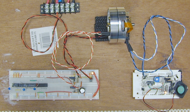
GTBecker wrote:Just a teaser: I'm not quite ready to discuss details, but this is a rotary transformer power supply that uses the video head drum (officially, it's called a head cylinder) from a VHS VCR. It is, essentially, an unusual switching power supply. It provides 1.2A at 5v and 150mA at 12v, both regulated. The input is 12VDC at ~1A, so it's about 65% efficient. The small blower on the right cools two 10ohm power resistors, a dummy load.
Image

I came across this post while looking for information on Rotary transformers..

I know this is off-topic but, I am using one for a different project, and from all other accounts I didn't know it was possible to transfer that much current through these VCR heads. Any more information that you would be willing to share on how you did it would be greatly appreciated!
By GTBecker
#134826
... from all other accounts...
When I was researching this I found nothing similar. Are there other methods?

Using H-bridges, I drove two pairs of paralleled fixed coils (there are four pairs of coils in the Sony drum I used) in quadrature with a 3MHz NRZ serial stream that also carried three data channels, generated in a GAL. The flying coil phases are individually full-wave rectified, then paralleled to produce a raw unregulated supply of ~16vDC. Switching regulators took it from there. The flying phases also feed a decoder that yields the input signals, in my project, the rotating platform shaft encoder quadrature phases and an index pulse.

Although the flying portion of the project only needed ~140mA, the technique was able to provide much more before smoking a coil.
By ericpwb
#134833
I should have been more specific... I am building a rgb propeller clock, and any place I have seen a mention of using a vcr head, except here, (which is only a few, the only one I saw with any explanation was here http://us.cactii.net/~bb/propclock/) stated that they were only getting about 120mA at 5v, which for my purpose won't quite do.

However, from your explanation, it seems that I have some learning to do before I get any further on this project!

Thanks for Your Help!
By GTBecker
#134836
ericpwb wrote:http://us.cactii.net/~bb/propclock/
A fun application, but he doesn't use the drum coils well.

His clock's base appears to drive a single pair of coils with a single-ended 12v peak-to-peak 100kHz squarewave (via JP2) carrier, and he half-wave rectifies it (from JP1) with a single diode on the flying clock before feeding a regulator.

He does use 12 volts but misses the opportunity to, in effect, use 24v peak-to-peak (100% better) by not driving the coil with an H-bridge, which reverses polarities on both sides of the coil for each half cycle. He could also full-wave rectify the flying coils, with Shottky diodes, and gain another >~100% with that.

Although adequate for his project, he has chosen a poor frequency; the drum coils (only a few turns each) are wound in a ferrite bobbin core that is much more efficient at higher frequencies than he uses. Not much energy is transferred at 100kHz; two megaHertz or so should be the lowest frequency for reasonable efficiency. Remember that these coils are designed to pass video so your carrier should be something of similar frequency.

Since there are several coils in a VCR drum (some have two, some four and some have six pairs), there are several transfer paths that can be used simultaneously. Simply paralleling the coils will help if the driver is sufficiently stiff (use MOSFETs) - but you must pay attention to the coil configurations (some are centertapped) and sense (adjacent coils share a common ferrite mass and can cancel one another). And you can use time to advantage by driving several coils in quadrature, in effect doubling the ripple frequency once rectified, making for easier regulation.

The amount of power the drum can transfer is ultimately limited by heat; inductive and resistive losses are unavoidable and produce heat. The ferrite bobbin will become warmer as you draw more flux through it and will result in either fusing of a coil wire or warping or ungluing the core. Ask me how I know.

This is a challenging and rewarding project in its own right - and provides a platform for all sorts of rotating electronics. A propclock is one, but one can do much better than he did.
By GTBecker
#134889
I realized that I still have the breadboard that is shown in the photo. It stirred a recollection of an important detail I learned.

One of the projects the method powers uses a rotating laser that draws substantial current, about an Amp, when it is operating but little when it is not. The rectified drum secondary voltage is on the order of 16v under load, but when the drum coils are lightly loaded the secondary voltage can be quite high - ~50 volts, as I recall. The DE-SW050 (5v) switching regulator does not permit input voltages above 30v; the 12v linear regulator, a 7812, is spec'd at 35v maximum input. So, under light load the regulators could be damaged by the resulting high voltage. I solved that with a simple circuit that effectively limits the voltage with a power FET shunt that starts to turn on at 25v or so, drawing current as required to limit the regulators' input voltage to a safe value.

If your rotating project draws essentially constant current this is not a concern, but if your display has a wide range of anticipated current demands you might need to tame the resulting varying secondary voltage.
By 99_Linc
#135052
Interesting question and replies, but for ME, I'd want to know what the interest was with such info. I mean, there are plenty of range finders out there already.

Obviously, any range finder measures the amount of time it takes to recieve a return signal, and lasers are no different,, secondly.

The advantage of a laser range finder, is obvious. You have more precise control of acquiring your target.

The webcam, is used to focus in on the target, and you can do so visually.

With an acousic range finder, you would have to electronically discern which acoustic emission source was the source you're looking for. This produces an acoustic signal that the sensor system locks on to.

Same for a heat sensor. It has to discern between emission sources.

A webcam, allows for the user to fix on any object and the laser simply follows the cam axis.

Click on lock, and software will follow that object, basically.

So, you really don't even need a laser.

You can use software to decide if the object is getting closer, or moving away, by it's getting larger or smaller.

So, curious about the OP's inention here.......LOL....

Range finding.........Hmm.......

LOL
By GTBecker
#135261
Here is an extract of one method. This uses a GAL to produce four 3MHz signals that switch the coil primary drivers in push-pull quadrature; note that the second pair of signals are 90 degrees delayed. The GAL also encodes some data, a shaft encoder quadrature pair and an index pulse. You don't need the GAL to do some simple clock division to derive 3MHz quadrature in upright and inverted, just some D-flops, but you will need a 12MHz oscillator. Of course, you can run at slower speeds but efficiency will be lower at lower frequencies. You can also use different drivers, or bare transistors, if you wish.
You do not have the required permissions to view the files attached to this post.
By Eggbert
#139838
Apologize for bumping old threads, but with so much useful info stuffed onto these pages I saw little point in posting a new thread on the same topics.

I'm in need of a laser range finder in the 50m min to 1000m max range, accuracy is not critical <2m is good enough, but I need fairly fast updates (at the very least several hundred Hz, hacking a commercial LRF won't get me there AFAIK). I have EE background, though never worked much on lasers or RF. I've got common electronics equipment like GHz scope, reflow solder equipment etc, but no optics-related measurement equipment of any kind.

My impression (please correct me here) is that I'd better be looking at an optical oscillator and a PIN diode, possibly with integrated preamp.. I guess my main question is what wavelength (and power) laser would I best be looking at to achieve the desired range (1km) in sunlight conditions, reflecting not off reflective bumper stickers but off dirt, soil and trees? Would an APD be required? Is it even feasible to achieve such range on an experimental basis? I do have access to CNC machining services, so precision mounts etc can be made for alignment.

Ignore the signal processing challenges for now, I work with that stuff so it's not a big deal to me, all I want initially is get the drive circuits and optics together and the scope plus a calculator will do the rest for the time being.

Kjetil
By fll-freak
#139859
What is your budget? If your purse is big enough, you might look at Analog Devices for a TEC cooled APD module for you receiver.

At 1000m your time of flight is about 6usec. This allows you 166Khz update rate before your pulses overlap. This does not sound like a problem as you mentioned a few hundred Hz. The recovery for your receiver and laser as well as the processing time will likely be the barrier for update rate.

Are you interested in a visible laser? What safety issues are involved? Must it be eye safe? Is your target orthogonal to the beam? Do you know what the reflectivity of your targets at the wavelength you pick? Do you have temperature limits? Shock and or vibe requirements? Size, weight or power requirements? Life expectancy at 100Hz?

You have a very large problem space. You need to start narrowing the field a bit!
  • 1
  • 7
  • 8
  • 9
  • 10
  • 11