SparkFun Forums 

Where electronics enthusiasts find answers.

Have questions about a SparkFun product or board? This is the place to be.
By GTBecker
#39545
Is there anyone interested in this or am I talking to an empty pipe?

busonerd, are you still doing an FPGA?
By busonerd
#39560
Hey,

I'm still around. I've been busy with paying work recently, so had to drop work on stuff for fun ;). Got a bit of the verilog written, just need to pull out my PC lappy and check the timing. I'll get to that sometime.

Cheers,

--David Carne
User avatar
By phalanx
#39563
GTBecker wrote:Is there anyone interested in this or am I talking to an empty pipe?

busonerd, are you still doing an FPGA?
I never posted but I've been reading. This is something I have always wanted to experiment with but like David, I've been so busy with work that pays that my hobby life has nearly come to a stand still.
By SOI_Sentinel
#39590
Interesting schematic. I actually bought an old TI Optoelectronics book a while ago because it has an IR LED/photodiode phase based discrete rangefinder schematic from a camera. I'll have to dig it up again.
User avatar
By bigglez
#39593
GTBecker wrote:Is there anyone interested in this or am I talking to an empty pipe?
Greetings GT,

I'm reading along - just don't have anything to add.

Comments Welcome!
By mooreaa
#39649
I'm definatly trying to understand and take in as much as I can here.

For now I am going to play with a laser and cmos camera sensor. I don't quite understand analog signal handling aspects of detecting the signal so I've got a lot of reading to do to understand this area more.

What I am stuck on is the sensitivity vs cost of optics.

Seems like busonerd willl come up with a good digital solution. So what about the analog side.

What is the basic circuit design needed to control the pulse generation as well as the receiver photo diode?

Also seems like given the issues with sensitivy a bandpass optical filter would help a lot? Whats available out there?
By GTBecker
#39656
mooreaa wrote:... a laser and cmos camera sensor. [] What is the basic circuit design needed to control the pulse generation as well as the receiver photo diode? Also seems like given the issues with sensitivity, a bandpass optical filter would help a lot?
CMOS cameras and photodiodes are two different technologies; they aren't related except that they are both made from silicon. The photodiode frontend schematic above won't help you with a camera, nor, I think, will the laser modulation schemes I've used be helpful.

The camera will determine what lens options you have, and the sensitivity curve of the camera sensor you choose will determine if you can use IR. Most Si sensors (CMOS, CCD, PINs, APDs and phototransistors) are sensitive to short IR (~900nm), but image sensors are sometimes fitted with an optical filter that limits IR sensitivity to maintain color accuracy. You can usually see the output from a TV IR remote control with an imaging sensor-based camera.

If you take the image sensor path, modulation will likely not be an option since each pixel in the sensor is probably inherently too slow to detect it unless it is very slow, perhaps near the image rate (assuming video, like 25, 30, 50, or 60Hz) to generate a detectable low heterodyne frequency. That, and optical IR filtering, narrow field of view, laser power (therefore contrast) and maybe anticipated motion, are some tools you can use to separate useful signals from ambient background and noise with an affordable image sensor, I suspect, but I have no direct experience with imaging methods.

You can find experimenter-grade optical tools at Anchor Optics http://anchoroptics.com/, American Science and Surplus http://www.sciplus.com/ and other similar outlets. An office supply can provide simple magnifiers and fresnel sheets. A stage lighting supplier can provide Rosco filters in any color but probably not an IR-pass filter. A used photography equipment house will have bins of old lenses and maybe even some Wratten filters, too, for cheap. Opaque plastic filters on remote controls and their counterparts on IR appliances like VCRs can also be used.
By mooreaa
#39670
GTBecker, I am not saying that I am takign the cmos camera in the same route. I am merely using openCV to get the pixel point of the laser dot. This method is crude at best which is why I originally came here to dicuss more advanced options.

I checked out the sites you mentioned for optical filters but didn't find anything in the red beam range for a bandpass filter. Perhaps I am looking for the wrong type of filter?

Based on the links that have been presented here, there was that $30 APD. If I recall right the only issue was that the beam would have be be focused back onto it very carefully. If so I would like to go forward with this and really try to put together an analog circuit that would be capable of triggering a laser as well as using the APD with the proper gains.

I've got a huge learning curve ahead of me, but I want to throw my self in because I really find this kind of tech interesting and I really want to understand it better.

I've seen two or three schematics posted here, I am not sure what the major diffferences are between them, and how they function. What are the principle techniques used to trigger the laser with minimal delay? And also how much gain/fitering on the APD is necessary before getting it into a digital form (IE what busonerd was talking about - high speed fpga based counter)?

Also busonerd (or anyone else), what Spartan Dev kit would you recommend? I havn't touched a fpga in a few yaers so gotta jump back in.
By GTBecker
#39673
mooreaa wrote:... didn't find anything in the red beam range ...
PN AX73990 Red, maybe?: http://anchoroptics.com/catalog/product.cfm?id=260

Image

And others at Edmund:
http://www.edmundoptics.com/onlinecatal ... uctid=2079

Here's a mounted 635nm filter:
http://www.allelectronics.com/cgi-bin/i ... LTER_.html

Rosco also provides transmission curves for its gels.
Last edited by GTBecker on Wed Dec 19, 2007 7:55 pm, edited 1 time in total.
By mooreaa
#39681
GTBecker wrote: Image
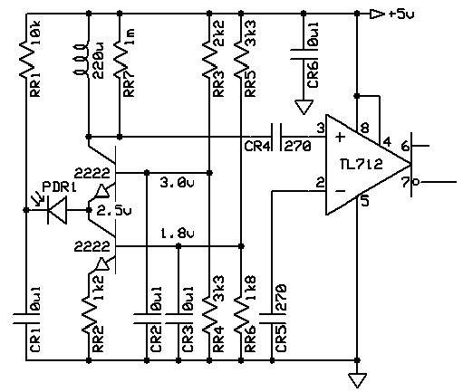
GTBecker, can you describe this circuit a little more? Is this what you are using on your system?
By GTBecker
#39684
mooreaa wrote:Is this what you are using on your system?
I've built several different receivers. This is one type that solves several inherent problems, is simple to build and works pretty well.

One objective is a fast photodiode, but photodiodes exhibit capacitance which tends to slow them. Photodiodes can be operated in several modes; one is voltaic mode, where it generates a voltage that changes with illumination. This is a good mode for linear accuracy but it is slow because the voltage must charge the diode capacitance. Another mode is conductive, where the diode passes a current that changes with illumination. Although less linear, this mode can be faster because the voltage across the photodiode can be made to be constant, avoiding the charge/discharge cycle.

In this circuit, two transistors are connected and biased so that the junction between them is at a fixed voltage, ~+2.5v here, by the emitter follower configuration of the upper NPN transistor whose base voltage is fixed by the voltage divider RR3/RR4. Since the photodiode cathode voltage is also fixed at +5v here, the voltage across the photodiode cannot change with changes in illumination and is fixed at 2.5v. That constant reverse-bias charge helps the photodiode respond quickly.

[Ideally, neither RR1 nor CR1 would be necessary if a quiet stiff reverse-bias source is available, but this single +5v supply requires some isolation and filtering to reduce supply-induced noise into the photodiode. This allows some voltage drop across RR1, and therefore the photodiode, which changes as the photodiode current changes, so it is not perfect but the change is small in normal illumination. Still, a smaller RR1 will make the photodiode faster at the probable cost of increased noise.]

The lower NPN transistor is configured as a constant-current sink, determined by its fixed base voltage from voltage divider RR5/RR6 and the emitter resistance RR2. The resulting current through RR2, and therefore the transistor's collector, does not change. The result is a constant-voltage/constant-current node at the junction of the two transistors and the photodiode.

When the photodiode current changes as illumination changes, the constant-current sink forces the current change to be reflected in the upper transistor's collector current, the only source it can come from. If a load resistor were substituted for the inductor, a changing voltage would be created across it as the current through the resistor and upper transistor changes. That changing voltage is AC and will pass through CR4 to the comparator. The effect is that a changing photodiode current results in a changing voltage without changing the voltage across the photodiode itself, therefore maintaining its speed. This two-transistor connection is called cascode and the current-to-voltage conversion makes it a transimpedance amplifier.

The inductor and capacitive coupling to the comparator's input impedance prevents constant (and low-frequency) illumination from passing through to the comparator. This makes the circuit insensitive to most ambient illumination (which must be below saturation of the sensor), making it a sunblind detector (a relative term; obviously, don't point this at the Sun, but the detector should work in daylight). If the inductor is chosen so that it resonates at a useful frequency, there is some voltage gain at that frequency and some loss at other frequencies, making the circuit moderately modulation-frequency selective.

The TL712 comparator is unusual in that the inputs are internally DC biased. That makes it a handy AC comparator, and it has 5mV of hysteresis at the inputs which reduces chatter from small signals. Its outputs are TTL, so a modulation-frequency logic signal appears on them. If you are building a TOF optical oscillator, these logic signals can be used to toggle the laser; the modulation frequency in that case is not fixed so the inductor resonance might be chosen for the lowest practical optical oscillation frequency to increase gain at longer distances that simultaneously suffer from inverse distance losses.

More AC gain will be required for a practical detector of some range, but this is sufficiently sensitive to see results from a bright return from a retroreflector, like that posted early in this thread.
Last edited by GTBecker on Sun Dec 16, 2007 7:05 pm, edited 3 times in total.
By GTBecker
#39694
mooreaa wrote:... that $30 APD... [] triggering a laser...
Again, you do not need an APD to get early results. Later, if you find you need more gain and have a good understanding of what you're trying to do, you might find an APD useful; at this point I suggest you use the PIN photodiode of your choice instead.

Triggering is not the correct term for the optical oscillator I believe you're trying to build; toggling is closer. Triggering applies more to the flash-pumped solid-state laser, meaning you have no control once it's lighted. What you'll want to do is turn the laser on and off at 50% duty cycle.

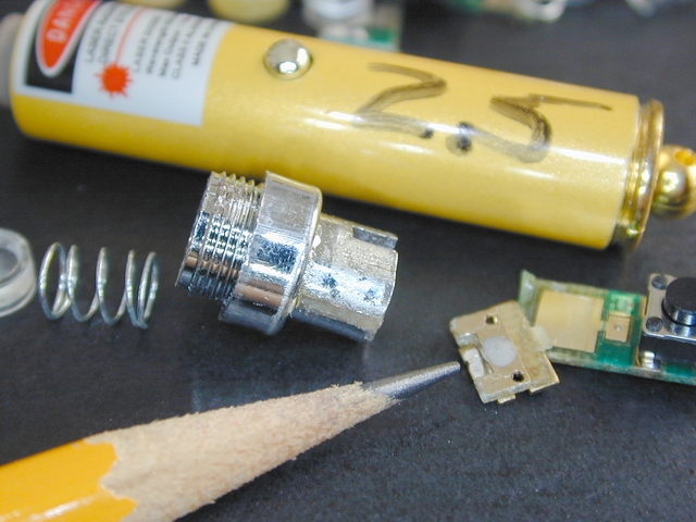
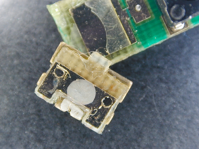
Here is a typical cheap 4.5v 2.5mW (measured) 655nm laser pointer and the guts of another. The laser diode slice itself is tiny, buried between two pieces of brass, fed by an extremely-thin whisker of wire - at the pencil point. Light is mostly emitted toward the pencil; a focusing lens is required to form a beam, a small heatsink is required to prevent melting the diode if you push it, and it won't take much current to vaporize the whisker if you pulse it with any appreciable current; it's tiny wire. [You'll smoke them, I guarantee, so have a pile of these cheepies on hand.] Not visible is the sole current control for these lasers, a few-hundred-ohm resistor in series with the diode slice, on the underside of the switch PCB.

Image
Image

More images of the laser pointer interior are in this document: http://www.earthsignals.com/add_CGC/hr/Wb_Laser.doc

Driving these is simple: a 7400-series TTL driver (I like fast and stiff 74AC14s) and a series resistor. You can start with 200ohms or so and decrease it later if you want to explore the edges of what these lasers can produce. Without warning, when you reach the point of destruction the laser will become very dim, permanently, and can literally produce a tiny puff of smoke if you drive it harder trying to get more from it after it has dimmed.

The power from these cheap lasers varies widely from piece to piece; most can yield ~3mW like this one, but others have been pretty impressive. I've measured some capable of 10mW average with fast square modulation, so the peak power can be 20mW from these things!, although I don't know for how long. That is an extremely intense and truly tiny point of light, so the power density is very high when focused on your retina and can be damaging. Always - even with these cheap lasers - avoid looking at the output no matter how tantalizing it will be. Better, wear appropriate safety glasses.


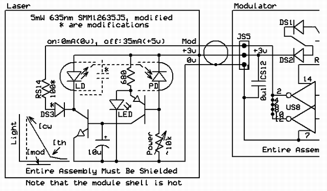
More costly laser modules contain an onboard power control circuit, with feedback from an integrated photodiode in the laser diode case, a windowed three-lead proper semiconductor device. All of these types of modules that I have worked with use a similar control circuit and can be modified similarly. Photos of this type of modified module are earlier in this thread.

This schematic shows how the controlled laser current can be diverted from the laser diode to quickly turn it off, while leaving the slow power control active. Normally, ~40mA is drawn through the laser diode by the NPN control transistor between its cathode and ground; if 35mA is injected at that junction, the current through the laser drops to near the threshold, just above zero. My experience is that a 5mW module can be operated at 10mW peak - and is, automatically, when squarewave (50%:50%) modulated - but you will need a laser power meter or a creative alternative to properly determine that operating point; the value of RS14 will also need to change if you change the laser power with the pot, and a larger RS14 is safer but modulates the laser less, reducing its effective detectable power. Don't divert too much current from the laser diode or it will be reverse-biased - often instant death to laser diodes. A capacitor across the laser diode must be removed for fast modulation - but you should know that this capacitor is a safety device that can save the diode from being fried by dV/dT glitches, though I am not aware that this has occurred to me. There is, still, every good chance that you will destroy some of these modules in development, too.

Image
Last edited by GTBecker on Mon Dec 17, 2007 7:57 pm, edited 3 times in total.
By GTBecker
#39721
I'd said earlier that the Miami laser module supplier I'd used was no longer in the business. Not so; his home page is broken but will be fixed soon. Meanwhile http://www.steminc.com/laser/laser.asp is a pretty good collection of these modules, all in stock, he says.
By GTBecker
#39803
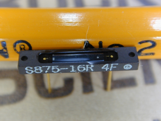
This is the Hamamatsu S875-16R that Electronic Goldmine currently sells very inexpensively. http://www.goldmine-elec-products.com/p ... ber=G15405 Of this discontinued part, Hamamatsu says: "I was able to locate only minimal data, not a full datasheet. The peak sensitivity does NOT occur at 875nm. It looks a lot like the S2387-16R. Rich Deneen, Hamamatsu Customer Support Engineer." Indeed, it behaves very much like the S2387-16R:
Image


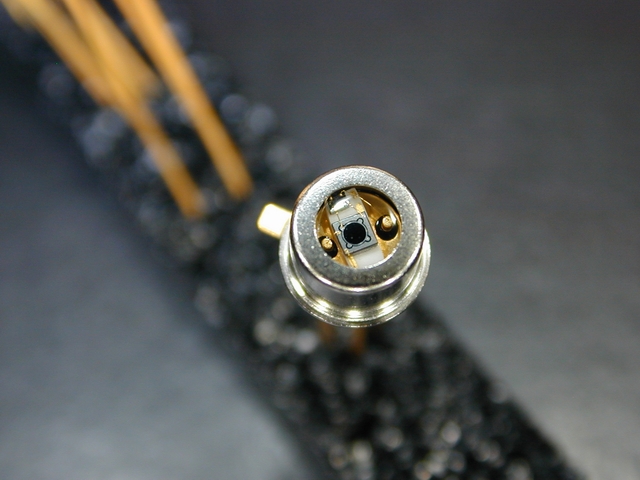
This is Edmund's 59-391, a preamplified 15MHz PIN sensor. This part, three small caps and a TL712 make a very simple high-speed logic-output detector. I tested such a circuit and it operates fine at 15MHz. However, the onboard amplifier is DC-coupled which makes this part unable to be part of a sunblind detector because it will saturate in daylight. Optically filtered to ~900nm, though, it should work well indoors or at night. The sensitive area is small, 0.8mm diameter. A faint laser-etched "6468" on the package reveals that this part is also a discontinued Hamamatsu component. http://sales.hamamatsu.com/index.php?id ... &undefined

Image
http://rightime.com/images/WAAS/edmunds ... _59391.pdf
By GTBecker
#39839
Physically constructing a narrow-beam laser system isn't trivial. Alignment is very important to the success of the system - and it can be a pain. Because the beam is thin and the sensor is small, the mounts, optics, sensors and supports - everything - must be be pretty rigidly built or it won't work just a moment after it did, sort of.

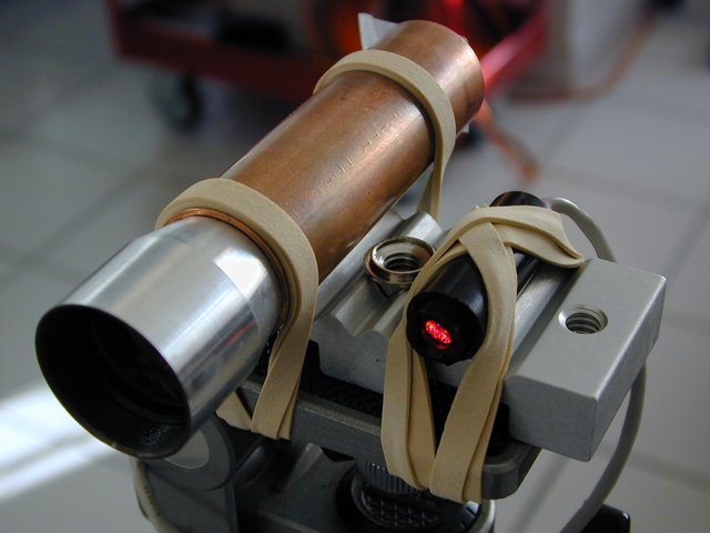
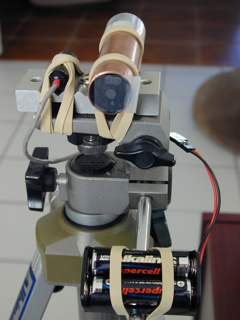
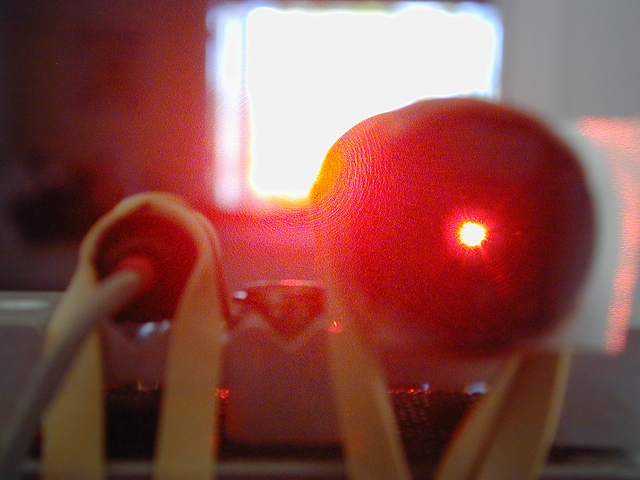
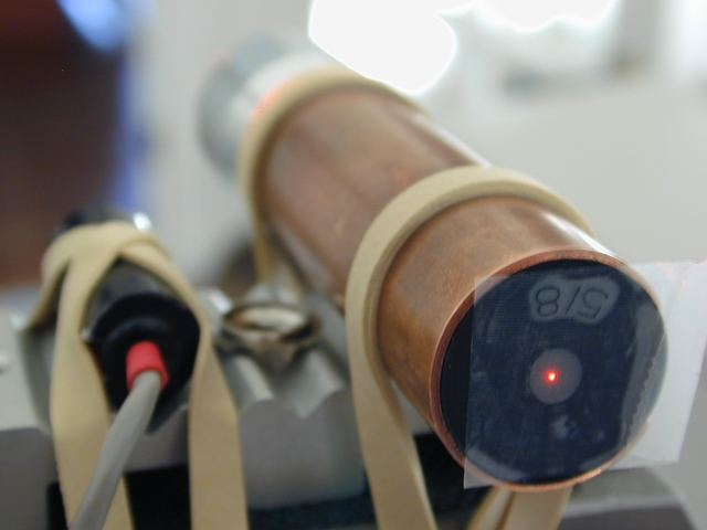
Here is one way to help keep the laser beam axis and the detector axis parallel, at least. I used an optical table wiring support that has convenient grooves in it, but you can rout notches or channels in a piece of wood, too. It mounts on a photography tripod. The receive lens is part of a cheap monocular http://www.allelectronics.com/cgi-bin/i ... ULAR_.html, centered and held inside a 3/4" thin-wall copper pipe with an o-ring which also optically seals the fit. This is a convenient lens, but most any simple lens will work if it can be mounted on center and sealed. The focal length of this lens is about 3"; to focus and center the beam return, infinity falls on the piece of Scotch tape on the ~5/8 (actually 13/16" OD) neoprene faucet washer that snugly fits in the pipe. The centered hole is, conveniently, 4.6mm diameter, perfect for a TO-18 or TO-46 can or a T1 3/4 (5mm) plastic phototransistor or LED (as a sensor). Ahead of the washer is a 635nm plastic red filter from an old LED display window, sandwiched with another washer. Ideally, the inside surface of the pipe should be made non-reflective; a rolled tube of flat black paper or dark felt will reduce loss of contrast caused by internal reflection.

If you build something like you'll find it is best to have just one movable optical part in the system; I've found that the laser lens can be moved laterally in its threads enough to center the return on the tape if the laser is focused on a distant white wall. You can use a distant retroreflector or reflective tape (maybe even a street sign), too, for a brighter alignment point. Once centered, the tape can be removed to insert the sensor, whose front-end electronics should be immediately aft. The entire assembly can then be moved to measure other objects.

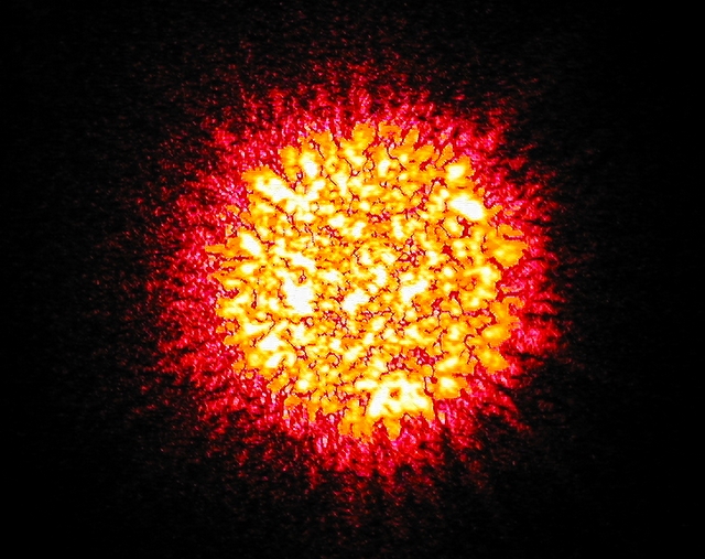
The sun-like shot is speckle from the reflector I used; this is essentially a magnification of the dot you see on the tape. Great art, huh?

Image
Image
Image
Image
Image
  • 1
  • 5
  • 6
  • 7
  • 8
  • 9
  • 11