SparkFun Forums 

Where electronics enthusiasts find answers.

Have questions about a SparkFun product or board? This is the place to be.
By AllenPitts
#179749
Hello SparkFun Forum,

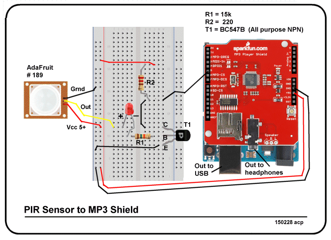
Working on getting a PIR sensor to fire an MP3 player.
I tried the code at
https://learn.sparkfun.com/tutorials/mp ... eld-hookup
This will play track 1 when pin 0 is shorted to ground
but shorting pin 0 again does nothing. One can short pin 0
get the track to play then short pin 2 and get results
and then short pin 1 and get results but shorting pin 1
repeatedly only provides results the first time.

So I wrote code but the code I wrote only allows a short
amount of the track to play unless the length of the
track is input as a delay and then it plays the track
in an infinite loop.

The function desired is
track is played when pin 0 is shorted
track is played again when pin 0 is shorted

What am I missing?

Thanks

Allen in Dallas
Code: Select all
#include <SPI.h>
#include <SdFat.h>
#include <SdFatUtil.h> 
#include <SFEMP3Shield.h>

SdFat sd;
SFEMP3Shield MP3player;
int triggerPin = 0;
void setup() {

  Serial.begin(9600);

  //start the shield
  sd.begin(SD_SEL, SPI_HALF_SPEED);
  MP3player.begin();
   //start playing track 1
  MP3player.playTrack(1);
   delay(6000);  
    MP3player.playTrack(1);
 
}

//do something else now
void loop() {

}
User avatar
By Ross Robotics
#179762
I don't see any reference of pin 0 being brought to ground. Another note, Setup only runs once. Once it's done it's thing nothing else will happen. Put your track playing code into void loop(). You also need to either bring pin 0 to a HIGH state or put a pull up resistor on the wire/pin so the hardware knows when it should be playing.
By AllenPitts
#179829
Hello CodlInk,

Sorry, posted the wrong code.
This code sets the trigger pin to high.
Then when the 0 pin is shorted to
ground it should
1. Play the track
2. Delay six seconds (the length of the track)
3. Stop the track
4. Set the pin 0 to high.

But the track loops forever.

Trying to get it to
1. The track to play when 0 pin is shorted (input
from the PIR sensor)
2. Stop when the track plays once
3. Play again when the sensor sends
another signal

How can I get it to do that?

Thanks.

Allen Pitts, Dallas Texas
User avatar
By Ross Robotics
#179836
What is grounding pin 0?
By Mee_n_Mac
#179842
Can you post a link to the PIR sensor used ? That # (150215) doesn't go to any product I can find. ATM I'll assume the PIR has some OC type output w/a pull-up to 5v. That it goes LOW when/while motion is detected. That you have that output connected to pin 0 of the Arduino. [FWIW I wouldn't use pins 0 or 1, they're already in use by the USB <->UART bridge. Pin D5 is unused.]

If I've got the above correct, then you should be able to modify the example code to do what you want. Post your attempt at that and we'll see what's up. One potential problem is this ... what happens if the PIR is continuously detecting motion and holding it's output LOW ? Depending on your code that could lead to continuously triggering the track over and over again. Remember that the Arduino is not controlling the pin, the PIR is. The code needs to look for the pin to be HIGH, after being being triggered, before it begins to look for the next LOW if you want to avoid this condition.

ps - pin 0 is the Rx input from the USB to the UART. If you've got traffic going from the PC to the Arduino, pin 0 will be going HIGH and LOW even w/o any detections from the PIR.
By AllenPitts
#180079
Hello SparkFun Forum,
Its has taken me a while to reply to Mee_n_Mac's excellent post because my son has been sick. I finally made it.
When I wrote "PIR Sensor 150215" the "150215" was the date: yymmdd. The PIR sensor, to answer the question is an
AdaFruit prt # 189
https://www.adafruit.com/product/189
The AdaFruit was used because it has adjustable timing and sensitivity.
The intent is to have the PIR sensor take the 0 pin high and trigger
the MP3player.playTrack(1). Then when the track is finished playing
set the trigger pin to low so when the PIR sensor sends another
signal the 0 pin will be low and the high signal from the sensor will
trigger another playing of track 1.
I don't know how to say "Wait until the track is finished
playing" in C so I put a six second delay because track
one is a bout 5.5 seconds in length but it would be better
if the sketch said "wait until the track finishes playing and take
the trigger pin low".

The code written compiles and loads but it plays the
track. But the track is played over and over in an infinite loop.

How can I get a high signal from the PIR sensor
to play track 1 and then when the track is finished playing
set itself ready to receive another signal?

Since the PIR sensor resets itself after three seconds
it would be good for the Arduino to ignore signals from
the sensor until the track has finished playing.

Thanks.

Allen in Dallas
Code: Select all
#include <SPI.h>
#include <SdFat.h>
#include <SdFatUtil.h> 
#include <SFEMP3Shield.h>

SdFat sd;
SFEMP3Shield MP3player;
int triggerPin = 0;
void setup() {

  //start the shield
  sd.begin(SD_SEL, SPI_HALF_SPEED);
  MP3player.begin();
}

//do something else now
void loop() {
  // main code here, to run repeatedly:
     // det trigger pin high
  triggerPin == LOW;
   // trigger pin shorted to ground plays track
  if (triggerPin == HIGH)  
   {
    MP3player.playTrack(1);    //start playing track 1
   }
    if (MP3player.isPlaying())
    {delay (6000);
    MP3player.stopTrack();
    //set the trigger pin back to low so the high signal will trigger
    //the MP3player
    triggerPin == LOW;
    }
}
By Mee_n_Mac
#180083
I'm not sure why your track loops forever, my quick look at your code indicates that it should never play. I see 2 problem areas; the hardware and the software. :o :twisted:

On the first ... you've got a 3V sensor trying to directly signal a 5V Arduino. Your sensor works the opposite of what I guessed above, it outputs a 3V pulse when motion is detected and is 0V otherwise. Alas 3V is very questionable to be detected as a HIGH when input to a 5V system. Maybe it'll work, maybe not. I'd put some interface circuit between the PIR and Arduino to make sure it worked. I'll say more on this after talking about the code mess. One last point re: hardware ... I don't know how you're powering the PIR but it's ground must be tied to the Arduino's ground in order for any signal to be passed. Some people forget this and that leads to unpredictable behavior.
R
Onto the code ... I said it once and I'll say it again ...
Remember that the Arduino is not controlling the pin, the PIR is. The code needs to look for the pin to be LOW, after being being triggered, before it begins to look for the next HIGH if you want to avoid this condition.

I'll assume you meant for the triggerPin to be the Arduino input pin that the PIR is connected to. If so then (again) I would chose a different pin than pin D0 for the reasons mentioned. Then if you want to know whether a pin is being held HIGH or LOW, you need to read the pin and then ask if it's HIGH or LOW.
http://arduino.cc/en/Tutorial/DigitalReadSerial
http://arduino.cc/en/Reference/PinMode
http://arduino.cc/en/Reference/DigitalRead

Do not try to turn the input pin into an output pin and drive it to some level, 0V or 5V. This would potentially put the Arduino circuitry "fighting" the PIR circuitry, to force different voltages on the same pin. Nothing good will result. To get around the possible continuous detection I would code the reading of the pin and commanding of the MP3 a little bit differently.
Code: Select all
#include <SPI.h>
#include <SdFat.h>
#include <SdFatUtil.h>
#include <SFEMP3Shield.h>

SdFat sd;                      //create an instance of SdFat named sd
SFEMP3Shield MP3player;        //create an instance of SFEMP3Shield named MP3player
int triggerPin = ??;           //this sets the pin the PIR will use
boolean triggerState = false;  //this variable indicates if detection is in progress
void setup() {
  //start the shield
  sd.begin(SD_SEL, SPI_HALF_SPEED);
  MP3player.begin();

  //you also need to set the input pin to be an input
  //this was missing from your code
  pinMode(triggerPin, INPUT);
}

void loop() {
  //if trigger pin reads HIGH then PIR is detecting
  if (digitalRead(triggerPin) == HIGH)   //see how this is different from your code
  {
    if (triggerState == false)   //only play track if not already played this detection
    {
      triggerState = true;       //set triggerState, reset only after triggerPin goes LOW 
      MP3player.playTrack(1);    //play track 1, will only happen once per detection
    }
  } else {
    if (MP3player.isPlaying() == false)  //triggerPin must have been LOW to get here
      {
        triggerState = false; //track must be done playing to get here, re-enable track
      }
  }
  // no need to stop the player after 6 secs, it'll stop on it's own
}
Please read the comments I've added. See how I don't fiddle w/triggerPin. See how the code avoids continuous play if the PIR is stuck HIGH for some reason. Note I've not set a pin to be used. The hookup guide shows D5 and D10 being unused. I'd pick pin 5 as the triggerPin.
https://learn.sparkfun.com/tutorials/mp ... eld-hookup

Now back to the potential problem of voltage mismatch. You could buy a level shifter, SFE sells a few of them, to shift 3V up to 5V to ensure reliable detection by the Arduino of the PIR output. But it's simpler to just make your own from a resistor and a common transistor. The circuit below will (effectively) make the PIR output into the OC type that I mentioned. That also means it will invert the sense of the signal. When the PIR is HIGH, the Arduino read a LOW. When the PIR is LOW, the Arduino will read a HIGH. That means changing some of the code above, including the pin definition to use the "input_pullup" declaration.
(click on to open)
2N2222driver.jpg
Note: R1 can be any value 1k (min) to 20k. Higher is probably better. Power needs only to be 1/8 or 1/10 watt. Q1 is a 2N2222 or 2N2222a (more common now). Note that I've show the GND signal tied to the PIR and Arduino and Q1. The Arduino's internal pull-up resistor is enabled.
You do not have the required permissions to view the files attached to this post.
By AllenPitts
#180125
Hello Mee_n_Mac and Sparkfun form,

The good news is I was able to compile and load
the excellent sketch posted 27 Feb.

Not having as much luck with hardware.
Image

Perhaps I didn't understand the schematic posted 27Feb
I got the PIR sensor to the transistor base to open the collector to the emitter
and allow a high signal to go to digital pin 5. (What difference does
it make if pin 5 is used instead of pin 0? Or does it make any difference?)
A LED and was added between the
the base and the sensor Out to get an indication.
I get the ground of the sensor and the transistor emitter going to the ground
of the Arduino.
Where it gets a little fuzzy is on the collector side of the transistor.
I have it going from the collector to digital pin 5. (I think that is what was meant
by 'D5' on the schematic). Then I have it tied to a resistor and then to the
Arduino Vcc 5+.

But this not working.

In fact I don't think the PIR sensor is working because the LED is not
lighting up. I measured the voltage with a multimeter between the
sensor Vcc and the sensor ground and got +4.9 volts so I don't
see why the sensor won't fire.
Do I have the breadboard right?
Thanks.
Allen Pitts, Dallas Texas

PS I really appreciate the help on this. I can tell you have spent some
time. If there is some way I can
reciprocate I am your humble servant. I have skills in drawing
breadboard pictorials and schematics. I also can build web sites.
If either of these skills are attractive to you are even $$, sticking
with me while I get this work would be appreciated with action.
By Mee_n_Mac
#180127
The 1st thing to do is make the PIR is working. So disconnect it's output from the rest of the circuit and measure it's output w/the DVM. If needed set the pulse width to it's max.

If it outputs a pulse the you need to checkout your BB. It looks OK to me but some measurements will tell us what's happening. It's possible that the PIR can't output much current and that's why the LED doesn't illuminate. So connect the output back into your BB and measure it again.

If you can see any action on the DVM then the pulse is likely good. Next measure the collector voltage. Without a pulse it should read 5v. With a pulse it should be near 0v. If you want, you can test it w/o the PIR. Just disconnect the PIR output from the BB and route 5v in it's place. In effect you've made a very long 5v "pulse". In fact you don't need the R2 resistor if the collector is connected to pin 5 and you've enabled the Arduino's internal pull up resistor. Simpler is generally better.