SparkFun Forums 

Where electronics enthusiasts find answers.

Have questions about a SparkFun product or board? This is the place to be.
By john93
#177958
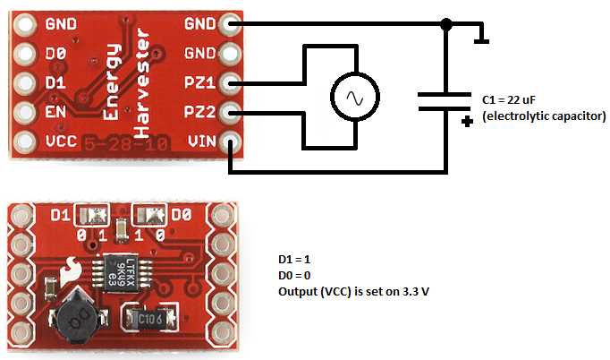
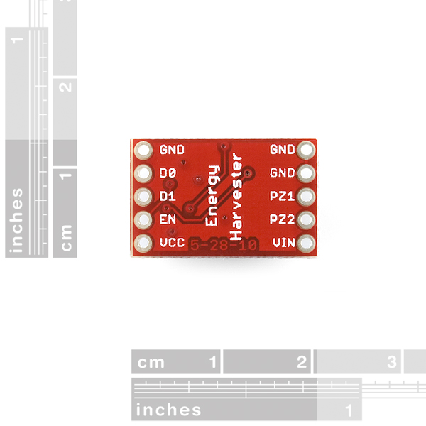
I have bought SparkFun Energy Harvester Breakout - LTC3588 board https://www.sparkfun.com/products/9946 recently.
However the board doesn't work properly - I suppose I make a mistake in my circuit.
Image
To verify if the board works properly I only connect to PZ1 and PZ2 function generator, I set as a signal - sine wave, amplitude up to 10V, frequency up to MHz.
Unfortunately, when I connect oscilloscope to VCC there is only electrical noise. Signal in VCC is not rectified at all.
Where do I make a mistake?
Sorry if I made wrong syntax - my mother tongue is not English.
By john93
#177975
jremington wrote:What output voltage did you select with D0 and D1? Each input must be tied to ground or Vin2.
It would help if you could post a complete circuit diagram of your setup.
Below you can find the complete circuit I made during verification of SparkFun's board.
As a AC source there is connected function generator (sine wave, up to 10V amplitude, up to a few MHz frequency).

Image
Mee_n_Mac wrote:Did you add a capacitor between Vin and ground ? It should be at least 10 uF per the datasheet.
Yes, I added 22 uF electrolytic capacitor.
By Mee_n_Mac
#177983
The only thing I can think of is to connect your function generator between a PZ input and ground and do a test. I ask this only because one of the function generator "outputs" might be grounded and grounding a PZ input might/maybe affect the functioning of the IC. Also try it at audio frequencies.

If that doesn't work, I agree w/jremington ... time for a new board.
By john93
#177985
Mee_n_Mac wrote:The only thing I can think of is to connect your function generator between a PZ input and ground and do a test. I ask this only because one of the function generator "outputs" might be grounded and grounding a PZ input might/maybe affect the functioning of the IC. Also try it at audio frequencies.

If that doesn't work, I agree w/jremington ... time for a new board.
Do you mean to connect function generator between e.g. PZ1 and GND or PZ2 and GND?
By Mee_n_Mac
#177988
john93 wrote:Do you mean to connect function generator between e.g. PZ1 and GND or PZ2 and GND?
Yes, that's what I meant ... but I've now looked at the internal block diagram and my test isn't going to work either. Did you try your test at low frequencies ? Are the function generators outputs (both) floating wrt ground ?
By john93
#178273
I have just received a reponse from technical support of SparkFun:
I've never heard of simulating a piezo input with a function generator but it seems to be not uncommon: "Regarding 4, a function generator set to high Z output with a series resistor can be used to simulate a piezoelectric generator."

You can also try applying a DC source (i used a 9V battery) to VIN and GND and checking VCC and GND with a meter to confirm that the regulator is working.
If I apply a DC source, the voltage regulator works indeed, so generally speaking the board works properly.

Could someone explain in a more detail how I am suppose to apply a function generator to PZ inputs to simulate a piezoelectric generator according to SparkFun instruction presented above? (I do not quite understand approach from response of SparkFun, the clearest for me it would be an electrical schematic, e.g. editing of my schematic using even Paint).

I have already given a response to SparkFun about more details regarding application of function generator, but perhaps on forum someone could help me faster.
Thank you in advance.
By Mee_n_Mac
#178328
Looking at the block diagram I can't see how connecting a function generator (at audio frequencies) between the PZ terminals won't work. Even if one of the function generators pins is tied to ground, that should only turn the full wave rectifier into a half wave one. Even if the function generator were set to have some high Z output impedance, the LTC3588 should still make a DC voltage w/o a load applied. Perhaps check both PZ inputs w/a DC voltage (to ground), to make sure both paths are good ?
LTC3588block_diagam.jpg
You do not have the required permissions to view the files attached to this post.
By falingtrea
#178375
Measure the voltage on VIn when you have the signal generator connected and running. You should see a DC voltage there. If not, then your signal generator is not on or the output voltage is not high enough. Also the input diodes are rated at 50 mA, so make sure your signal generator is not overdriving them current wise. That may be why series resistors are recommended on the signal generator outputs. Charging a capacitor through the diodes with out some sort of current limiting could burn out the diodes. Piezo parts are high impedance so they don't generate much current, whereas a signal generator is not.