SparkFun Forums 

Where electronics enthusiasts find answers.

Have questions about a SparkFun product or board? This is the place to be.
By mikelaurey
#157449
I need to control a linear actuator (forward and backward) which takes 13A max at 24VDC.
Usually, when I need to do this, I use a battery to power a driver which directly power the linear actuator and everything works great.

The problem is that, in this case, I can't use a battery and I can only use AC power source (220VAC).
I tried to use a trasformer which takes in input 220VAC and give me an output of 24VAC - 10A with a rectifier in order to obtein a power source of 24VDC - 10A max for the driver; this system worked well for some days and then the rectifier failed. I think this happened because the driver is able to recover power from the motor inductance and send it back to the battery and this is dangerous if a transformer is used in place of the DC source.

I would like to ask you if there is a better solution to power and control my linear actuator by using an AC source without burning the rectifier.
Is it possible to use an H bridge, for example? I only need to control the actuator motion and I do not need to control also its speed or other parameters.
By waltr
#157452
Your problem sounds to be that the DC PS you built was under rated. You used a 10A diode for a 13A motor thus it burned up.
Even if you only draw 10A the diode would not last forever. Use a much larger diode for the rectifier, like ~20A.
Also, exactly which diode did use use?
What is the diodes reverse voltage rating?
Did you put any caps after the diode to filter the AC ripple? A single diode is a "Half Wave rectifier" (google this to learn what the waveform looks like and why filtering is a good idea).

You just need a better AC-DC power supply.
An H-bridge will not solve the above problem.
By mikelaurey
#157453
Thank you for your reply.

I used a bridge rectifier rated for 35A.
This is the datasheet: http://docs-europe.electrocomponents.co ... dadbc1.pdf

So, I used the transformer which takes in input 220VAC and give an output of about 24VAC - 10A connected to the bridge rectifier.
I've read 24VDC at the bridge rectifier.
Then I connected the bridge rectifier to my driver in order to control my linear actuator.

I didn't used any caps after the diode.

Can you give me some suggestions in order to improve my AC-DC power supply, please?
By Mee_n_Mac
#157458
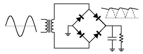
This pic describes your situation. W/o the cap the output waveform that you think is 24VDC looks like the dotted line.
Image
Your next question is what size cap should you use. That will depend on how much droop or ripple (see the drop in voltage between the peaks even with the cap, solid line) is tolerable. But as big as you can fit, 20,000+ uF would be a start. The challenge will be to find a large capacitance, with a voltage rating plus safety margin at 24 VDC, that will tolerate the large charge/discharge currents.
By mikelaurey
#157460
Thanks for the suggestion and your explaination.

So, I think my circuit should be like the one I've attached in this post.
What about the resistor value? Is it ok to use a 10K?
Won't the resistor generate a short circuit between GND and +Vcc?

@waltr: I do not knopw the dash number, on the bridge there is this code: KBPC3510.
I wasn't using any heat sink but it burnt with fire and smoke before to die.
The system does not have to work very frequently, just few minutes per day.
You do not have the required permissions to view the files attached to this post.
User avatar
By CircuitBurner
#157469
I think the resistor only represents the potential load of the circuit drawn, your "driver" prolly takes the place of the represented load.
By waltr
#157471
What about the resistor value? Is it ok to use a 10K?
Won't the resistor generate a short circuit between GND and +Vcc?
What is a 'short circuit'??
I consider it a short if the current is much higher than the PS is designed to provide.
Use Ohm's Law to calculate the current through the 10k Ohm resistor. Can the PS handle that?

The diode pn KBPC3510 would be the -10 column in the data sheet. So it should have survived any voltages present.
I have the feeling that the poor diode just over heated and then catastrophically failed (shorted internally). It is designed to be used with a heat sink.
By Mee_n_Mac
#157476
mikelaurey wrote:So, I think my circuit should be like the one I've attached in this post.
What about the resistor value? Is it ok to use a 10K?
Won't the resistor generate a short circuit between GND and +Vcc?
I agree your circuit should look like the one you've posted.

The resistor in my diagram was, as CB said, intended to represent your "load", aka the driver and linear actuator. If there is no load the droop btw the charging peaks would be practically nonexistent. The load draws charge off the capacitor causing it's voltage to drop ... until the voltage from the rectifier again becomes high enough to re-charge the cap. This all said I'd put a 10k resistor where you show it so the cap can be guaranteed to eventually discharge through it to zero volts. Less chance of an accidental high current discharge that way.

10k is not a short circuit in most any consideration.

As to why the rectifier burned up ... I can't say for sure. Perhaps the voltage (w/o the cap) got so low that the actuator stalled and drew too much current for too long. My guess is the 13A is some peak current that normally lasts for as short time. Can you provide any specs for the actuator and driver ?
By mikelaurey
#157479
Yes, the linear actuator is this: http://www.linak.com/corporate/pdf/ENGL ... et_Eng.pdf
It takes 10.4A with full load and 2.4A with no load; it can have peaks for 13A max.

The driver is this: http://roboteq.com/files_n_images/files ... asheet.pdf
It has an input voltage up to 50V and it can drive up to 40A in single channel mode.

Do you think I should have to use a higher bridge rectifier?
By waltr
#157481
I just saw this in the controller data sheet:
Important Warning:
Beware that regenerative braking can create high voltage at the controller's power inputs. Use the controller
only with batteries. See user manual for special precautions when using a power supply.

This may have caused the diode rectifier to short.
By mikelaurey
#157482
Yes, it's what I've said in my first post :(
In the manual, it says that it's better to use a battery in parallel with the power supply if it is necessary to use it.

Since I can't use batteries, Is it not possible to solve this problem?
The driver manufacturer said me that it is possible to use a power supply without giving me any warning about the battery.

However, regeneration problem occurs only when motor spins faster than the normal; I'm just using a linear actuator to move an heavy load up and down so the motor within the linear actuator should not work as generator any time in this case.
Can the linear actuator work as a generator when it moves the load down? :think:
By jremington
#157485
I think the regeneration idea has surprised most readers of this post, but yes, if that is what is causing the bridge rectifier to fail, then downward motion of the actuator is the most likely source of the problem (since the motor is "gravity assisted").

A suggestion might be to put a large diode between the power supply and the controller; one that is capable of withstanding considerably higher reverse voltage than the diodes used in the bridge rectifier. This diode will generate a lot of heat during normal forward conduction (full motor current) x (forward voltage drop of 1-2 V) watts, and so must be heat sinked.

I would hook up a meter to monitor the voltage input terminals of the controller during up and down motion to see what sort of voltages appear. The manual for the controller has an entry for the "maximum regeneration voltage at the motor leads" (Table 6 Note 2), and I suspect this means the motor shouldn't produce more than the stated value when spun up. Could it be that your linear actuator is exceeding this value?
By Mee_n_Mac
#157486
Questions for the OP :
1) Does your linear actuator have the clutch/brake option ?
2) What kind of load is the LA pushing/pulling ? Are you closer to the min load or max load for your LA ?
3) Does the load move at all when the power is removed ?

I'm thinking the LA is a motor that moves a threaded rod to get the linear action. Like a worm gear, I don't think much reverse motor-as-a-generator action can happen with this LA. The driver may warn about it but I'm guessing this load (the LA) doesn't make that happen. The failure is probably because the rectifier wasn't heat sinked and the drive was having a hard time with the full wave rectified but not smoothed power input. A large cap is needed in any case and will act like a battery to damp down any voltage rise due to regen. I say add a BFC and a heat sink and see what happens.
By mikelaurey
#157489
My linear actuator has two end stop switches: so, when it stops and shutdown by itself when it reaches the maximum and the minimum extension.
It also has an integrated brake for self-lock ability and a non-rotated piston rod eye.
In addition, it is rated up to 10.000N (about 1000Kg) both in push and pull and I'm using it to push up and down a load which is about 200Kg.
It works with an endless screw moved by a DC Permanent Magnetic motor.

For all these reasons, when the linear actuator is not powered, the load don't move and it is stable; I think that there isn't any regeneration during the down motion.

When I connect the driver to the rectifier output, I can measure something like 34VDC at the driver voltage input terminals even if the linear actuator isn't moving. (It should be 24VDC)

- I have a diode rated up 80A and 1000V and I can use it, if it is necessary (should I insert it between the transformer and the rectifier or after the rectifier and before the driver?).
- Should I just add the large electrolytic capacitor or also the big diode? (I just found capacitors rated for 25 - 35V max and larger than 20.000uF)
- Would it be fine to add also the resistor in parallel to the large capacitor?
In the meanwhile, I've found a large heatsink for the rectifier.

EDIT:
It is very difficult to finf a large capacitor from my local dealers.
I've found online an electrolytic capacitor 33000uF at 35V with a ripple current of 7100mA.
Do you think is it OK?