SparkFun Forums 

Where electronics enthusiasts find answers.

Have questions about a SparkFun product or board? This is the place to be.
By snifagoose
#157392
Hello,
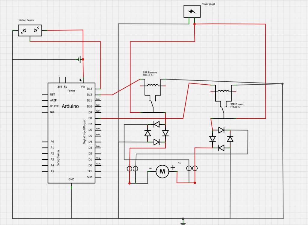
I am attempting a DIY project that will be requiring a small amount of sparky goodness and micro-controlling. The aim for this project is to be low cost, and because of this I am trying to use some existing equipment that I already have to work around. Without getting too involved with the gruesome details of the project, in a nutshell I am trying to control a low rpm high torque 115VDC motor, keyed by the nifty PIR motion sensor.

Here is the breakdown of my design challenges. (Keep in mind that I am doing this project for the challenge, and that I am very new to the micro controller sparkfun world)

1: I am trying to select the right micro controller, I have looked into the Arduino R3, the Wixel, and the Arduino mini. From what I gather, the Wixel has some very user friendly programmer apps that I can use that will make the programming less of a headache. However, I am intrigued by the coding aspect of the project and would love to sit down and write the code for an Arduino just to learn a tid bit about writing code. (I have very basic C++ training)

2: Given the 115VDC motor that I am using that is almost perfect for the application, I am struggling to find a way to integrate such a high voltage motor into my controller circuit. I have contemplated using the H-Bridge Driver - NJM2670E3 in order to drive the motor at around 55-60VDC, given that I am not worried too much about the speed of my motor. Any thoughts on a similar style, cheap driver, that will allow me to use the full 115V of my motor? If not, would the above mentioned H-Bridge driver be suitable to drive my motor forward and backward using one of the micro controllers from my selection?

3: Lastly, I am trying to use the PIR motion sensor to key the motor. Once the motion sensor is triggered, I want to program the controller to have a time delay and then power the motor. Any starting tips for how to set this up in Arduino code? Just some simple pseudo code logic is what I'm looking for here.

Any and all help will be greatly appreciated, I am already having a blast just planning this project out. Thanks!
By Dave Mueller
#157395
What's the current draw of the motor? For a few amps, you can use a relay. Drive the relay coil through a bipolar or FET from the micro. Once you go past the 7 or 8 amp level, you really should use a contactor. Mechanical methods (ie relays) work well for low duty cycle, on-off control of big loads. There are also "solid state relays" (SSR) that have logic inputs and can control AC loads up to 20A, but they get expensive.

From your description, the code should be relatively simple and almost any microcontroller should work. If you think you'll be continuing down the uC path, buy the Arduino R3 to design and test your circuit, then move to a Mini for a "finished product". That way you can use the R3 for future projects.
By snifagoose
#157417
Thank you for your feedback. The current draw for the motor is about 1A, so I am opting to take the SSR approach because I just so happen to have two of them laying around. They are pretty old, but they have a control voltage range of 3-32VDC which is perfect for the digital output of the Arduino. Now all I have to do is wire up the Arduino and write some code to integrate the motion sensor and I think I will be off and running. Cheers!
By Mee_n_Mac
#157428
Errrr, what arrangement are the 2 SSRs you have ? If they are the common SP-NO type you'll need more than 2 to have forward, off and reverse.
By snifagoose
#157450
They are SP-NC... They only open when the control voltage is applied. Hopefully this eliminates the need for more of them to keep the motor in the off position. This will however, require a close examination of the coding to ensure that both relays are not energized at the same time.
By Mee_n_Mac
#157456
Nope, you'll need 4 to do the same thing an H bridge does. Two at the + motor terminal and two at the - terminal. And of course you have to make sure that the two at any one motor terminal are not on at the same time. That would short 115VDC to ground. And this makes me very worried about how you'll prevent this from being the case as you power up the Widget and the code needed to output the "off" signal hasn't had a chance to run. That is, you'll need a way to keep the 115VDC away from the SSRs until the control signals to them are present and accounted for. Otherwise it's magic smoke time on power up.
By snifagoose
#157497
That is my goal... to account for the control signals to the relays before any high voltage is introduced.

Here is a link to the relays I am using: http://www.opto22.com/site/pr_details.a ... tem=120D10

I am using the Arduino 5V to activate the relays, which supply 120VAC to bridge rectifiers that are wired to the +/- terminals on the 115VDC motor. I have checked the output voltage from the bridge rectifiers using a multimeter, and the average DC power I'm seeing is about 114V.

Anyhow, I guess my thought was to wire each relay (only using 2) to the Arduino, and just switch the positive and negative terminals on the motor by using one relay or the other. Is this a bad way to set this thing up? I can always buy a couple more SSR's.
By Mee_n_Mac
#157502
snifagoose wrote:Anyhow, I guess my thought was to wire each relay (only using 2) to the Arduino, and just switch the positive and negative terminals on the motor by using one relay or the other. Is this a bad way to set this thing up? I can always buy a couple more SSR's.
From what you said before (I've not read the docs) your SSRs are a simple switch, closed or open. So let me ask you how you can put the motor in reverse with just 2 such switches ? Forward on the motor means 115 VDC on the + terminal and ground on the - terminal. Reverse means 115 VDC on the - terminal and ground on the + terminal. Try and draw a diagram with just 2 open/closed switches that does forward and reverse.

As for the "average power" you're supplying to the DC motor, you might want to read this thread and see if the waveform you're supplying (w/o any caps) is what you really want.
https://forum.sparkfun.com/viewtopic.php?f=14&t=35238
By MichaelN
#157523
I too worry that you’ll release the “magic smoke” with your proposed scheme. Also, as Mac points out you’d need 4 of your relays to build a H-bridge.

If all you want is forward-off-reverse control, I suggest you use old-fashioned DPDT relay to reverse the polarity of the voltage sent to the motor. This will only cost a few dollars, and will prevent accidental shorting of the supplies. To achieve the “off” function, you’d add another relay (your solid-state relay would do the trick).

Speed control could be achieved by replacing this solid-state relay with a MOSFET being driven by PWM (although a dedicated H-bridge chip would be better if this is what you’re after).
By MichaelN
#157524
I also forgot to mention that the peak voltage of a rectified 120VAC is almost 170V. If you have a filter capacitor after the rectifier, you'll see almost 170VDC unloaded - probably too much for a 115VDC motor.
By snifagoose
#157557
MichaelN wrote:I also forgot to mention that the peak voltage of a rectified 120VAC is almost 170V. If you have a filter capacitor after the rectifier, you'll see almost 170VDC unloaded - probably too much for a 115VDC motor.
I have no filter capacitor after the rectifier... This is beginning to make me wonder if I should look into a different method to power the motor.
Mee_n_Mac wrote: Your next question is what size cap should you use. That will depend on how much droop or ripple (see the drop in voltage between the peaks even with the cap, solid line) is tolerable. But as big as you can fit, 20,000+ uF would be a start. The challenge will be to find a large capacitance, with a voltage rating plus safety margin at 24 VDC, that will tolerate the large charge/discharge currents.
As you mentioned in the other thread, how would I go about figuring out how much droop or ripple is "tolerable"?

Also, here is what I drew up for wiring this thing...
Image
By Mee_n_Mac
#157566
I will assume that your drawing of the SSRs as a SPDT switch is just a mistake and that, in the switch position shown, the 120 VAC hot is NOT connected to the Arduino. Instead that's just the off position and there's no connection being made from the hot on the wiper to anything on the other side of the SSR.

However look at what happens when the switch goes to the other position. The 120 VAC hot get connected to the 120 VAC neutral, which is a short circuit and will fry both SSRs and hopefully trip the CB in your house.

Then you've got the dual fullwave bridge rectifiers. What was your intention with those ? As shown they would short the rectified AC at both the motor + and - terminals. I think I can see what you were trying to do; switch the AC into the rectifiers and have each bridge do the polarity switching.

Can you post a link to the motor you'd be using ?

Here's my thinking ATM. I am more than a little concerned. You've got lethal voltages in your circuit (170VDC is a lot worse than the 120 VAC and that can kill you) and you don't seem to understand how to wire things up. I've never seen a 120 VDC motor that will only draw only 1A. SSRs for switching DC are different animals than SSRs for switching AC. I had thought you had two DC versions "lying about" to use (my thinking was you were using them at the motor's terminal) and you've got them switching the AC waveform (before rectification). Which is somewhat good since the SSRs you linked to are AC types. And I don't think they are NC. At least they weren't specifically called out as such.
By Mee_n_Mac
#157570
Here's a fixed up version of your schematic that I think shows what you intended. See if this is what you wanted.

(click on to open and enlarge)
MasturdWiringDiagram_mod.jpg
One problem is that you are running the motor off the rectified, but not smoothed, "DC" waveform. If you put a cap across the motor to effect smoothing then you may have a problem when going from FWD to REV (and REV to FWD) in that the cap will have 170 VDC opposite of the polarity of the new command. You'd have to wait a time btw switching for the cap to bleed off through the motor.
You do not have the required permissions to view the files attached to this post.
By snifagoose
#157666
Firstly, thank you for all of your help and input Mac (and CB), I really appreciate it. This is exactly why I put my project in this forum before I did anything. Anyway, your edits to my schematic represent what I was thinking exactly. The software I used for the schematic didnt have a SSR configured the way you have drawn it to represent the relays that I have.

I guess the underlying question for this project is how I should power this motor. If this these rectifiers that I have are going to ruin the motor, or provide a waveform that is not acceptable, then maybe I should go a different route. Once I get that sorted out I can either use my existing SSR's or buy a DPDT relay that would achieve what I want in a safe manner. How do I know if I need a cap across the motor to smooth my waveform? Isnt PWM essentially using a similar method to control motors such as this? Pulsing electricity to the motor in order to maintain the set duty cycle? This "pulse" like wave I will be getting out of the rectifier is doing almost the same thing, right? The only difference being that it is outputting voltages up to 170VDC at the wave max amplitude for fractions of a microsecond?

Here is a link to the current model of the motor that I have. The actual motor I have has a model number of 313046 and a voltage of 115VDC stamped on it, but when I called the RAEmotor Corp this is the motor they gave me the specs from.

https://www.rapidindustrialsupply.com/m ... il200.html