- Thu Aug 02, 2012 8:44 pm
#148136
The boards and all the components have arrived !!!!!
I will be soldering the components this weekend. Meanwhile I have looked into software aspects of the project. Couple of things I would like to discuss
1) Compiler and IDE: The only full featured and free version of IDE that I have found is http://www.CooCox.com. I have downloaded it and poked around a bit, I looks good so far. Do you guys have any other suggestions?
2) RTOS or No RTOS: Should we use a RTOS or do bare metal programming?
3) Communication Protocol: What kind of communication protocol should be used between Vision Module and embedded device?
a) CMUCam 4 has ASCII based terminal like interface. It is easy to use in a interactive mode with a terminal, but not so good when it is used to used through a program or microcontroller.
b) PIXHAWK UAV project has a well defined protocol MAVLink. Looks interesting, but will require some work to port it for our use.http://qgroundcontrol.org/mavlink/start
c) Anything else out there??
d) Develop our own simple protocol tailored for our application.
Appreciate your thoughts and comments.
Cheers
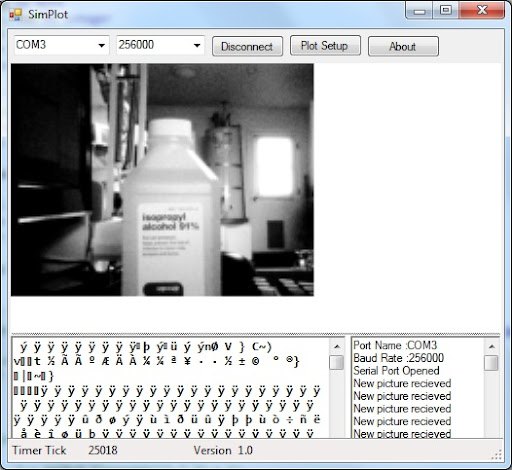
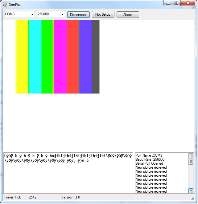
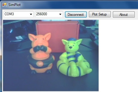
SimPlot: Real Time Plotting Tool.http://www.negtronics.com