- Sun Oct 17, 2010 11:35 am
#111591
Hi there 
I'm rather new in this field, so please bear with me.
Intro:
The primary aim of this project is to learn more about the basic electronic components and computation (plus having something completely awesome, yet entirely pointless to show my nerdier friends ).
).
Aim:
To build a 2-bit ALU with NPN transistors, resistors and LEDs only.
Schematics:
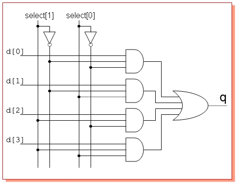
http://en.wikipedia.org/wiki/File:2-bit_ALU.png, replacing the two 8-bit muxes with 4-bit muxes as per http://electrosofts.com/verilog/mux_circuit.jpg
Conditions:
A) Inputs (2 numbers, each 2 bits wide as well as the mathematical operation to perform, 2 bits wide) are set by simple SPST switches
B) The 2 bit output should be represented by 2 LEDs
C) All logic gates should be constructed from NPN transistors and resistors only (http://alansouthall.files.wordpress.com ... -03-pm.png). Each gate should have an LED indicating the state of the output pin.
D) Power source should either be a 9V battery or a USB port (5V)
My questions:
Is this project plan at all feasible? After sitting down and trying to simulate one of the muxes in such setup I found it tremendously difficult to make it work. It requires ridiculously high current, and output voltage is far too small to switch a LED on (all my LEDs require around 2.3-2.6V). I tried to adjust resistor values (replacing the 10k and 330 Ohm resistors demonstrated here with 10 and 100 Ohm resistors respectively), which helped to a certain degree (I can see change in output voltage), but it's still far too small to power a LED.
Should I perhaps instead use two power sources: one for logic and one for LEDs? Do you have any other tips to get me going?
I'm rather new in this field, so please bear with me.
Intro:
The primary aim of this project is to learn more about the basic electronic components and computation (plus having something completely awesome, yet entirely pointless to show my nerdier friends
Aim:
To build a 2-bit ALU with NPN transistors, resistors and LEDs only.
Schematics:
http://en.wikipedia.org/wiki/File:2-bit_ALU.png, replacing the two 8-bit muxes with 4-bit muxes as per http://electrosofts.com/verilog/mux_circuit.jpg
Conditions:
A) Inputs (2 numbers, each 2 bits wide as well as the mathematical operation to perform, 2 bits wide) are set by simple SPST switches
B) The 2 bit output should be represented by 2 LEDs
C) All logic gates should be constructed from NPN transistors and resistors only (http://alansouthall.files.wordpress.com ... -03-pm.png). Each gate should have an LED indicating the state of the output pin.
D) Power source should either be a 9V battery or a USB port (5V)
My questions:
Is this project plan at all feasible? After sitting down and trying to simulate one of the muxes in such setup I found it tremendously difficult to make it work. It requires ridiculously high current, and output voltage is far too small to switch a LED on (all my LEDs require around 2.3-2.6V). I tried to adjust resistor values (replacing the 10k and 330 Ohm resistors demonstrated here with 10 and 100 Ohm resistors respectively), which helped to a certain degree (I can see change in output voltage), but it's still far too small to power a LED.
Should I perhaps instead use two power sources: one for logic and one for LEDs? Do you have any other tips to get me going?