SparkFun Forums 

Where electronics enthusiasts find answers.

Have questions about a SparkFun product or board? This is the place to be.
By haseeb
#75449
Hello

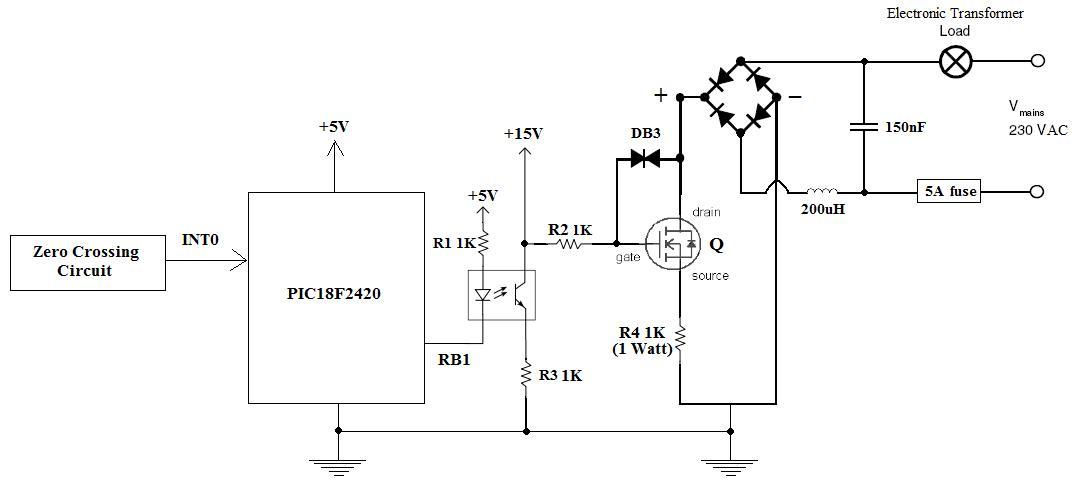
Im building a 1kW reverse phase dimmer (230VAC) using PIC MCU and a power MOSFET. This dimmer is designed for the dimming of ELECTRONIC transformers only. My circuit schematic is shown on the weblink.....

http://www.electro-tech-online.com/atta ... ircuit.jpg

Details of the power MOSFET (Q) in use are as follows....

# Manufacturer: INFINEON
# Manufacturer Part No: IPP60R099CPA
# Transistor Polarity: N - Channel
# Voltage, Vds Typ: 600V
# Current, Id Cont: 31A

The inductor and capacitor combination in the schematic is an RFI filter.

I simply wish to have my complete schematic cross checked for any mistakes so that the circuit can work as a reverse phase dimmer. Please can someone go through my schematic and kindly suggest any improvements that might be required. If there is any mistake, then please also point out and suggest the necessary fix.

Thank you
Haseeb
By madrang
#75485
if you want a dimmer the best solution is to use a triac and a way to know when to start your ac cycle and trigger it a the right time so you can have the % of the cycle that you want. i am currently building a schematic for you but try to post more detail please so i can do it to fit your need...
By madrang
#75487
The opamp is used to send a pulse at each start of an Ac cycle and on this shcematic is powered at 12V, so it will give a 12V pulse, you can also power it at 5V to have a 5V pulse. But be sure to always keep the pin 2 and 3 (invert and non-invert) inside the power supply so in this case not under Gnd and no more than 12V or 5V if you use 5V power supply. Use a transformator to keep the voltage low..(this to work only need 3 volt peak to peak)


This can be used with an Arduino, PIC or any TTL based micro controller (i suggest to use one that can handle interrupt).
After a pulse the cycle start so the charge have no power. The sooner you enable it more power you have. At each pulse the TRIAC reset it self (it does it alone this is why we use a TRIAC) and you just need a little pulse to turn it on for a whole cycle and cant turn it off until the Ac cycle is ended (note the number of pulse and the number of time the TRIAC need a pulse depend of the Hz of your Ac line)
Image
By abb51
#75491
I wasn't sure what "reverse phase" meant, so I went googling. (seems to mean using a switch rather than a resistor. fair enough)

I also found this page which happens to have a schematic for a 1kW dimmer: http://www.epanorama.net/documents/ligh ... immer.html


You mention you want to dim "ELECTRONIC transformers".
Do you mean switch-mode power supplies?
If so, you can't really dim them, the controller chip will just make it draw more current out of the portion of the cycle it has power available (or it might not turn on at all dpending on how much of a cycle it gets)
I've seen a switchmode supply fighting a dimmer on a CRO, it's not pretty.
By haseeb
#75503
Hello people

thanks so much for all your support. ....Madrang......thanks for the diagram....i appreciate your kind consideration.

okay so not let me explain what am i intending to achieve here.....

This circuit that I posted earlier is actually for the dimmming of 12V halogen lamps via transformer couple.....thats why the transformer load.....However the transformer on the HT side will be an electronic transformer.

Because these transformers are capacitive load in nature (V lags I)...therefore....for these types of transfromers, i have read on the internet that you need a reverse phase dimmer to achieve flicker free dimming....and one achieves this via Power MOSFET or IGBT etc....essentially a transistor....not a TRIAC. In reverse phase dimming you turn on at the zero crossing and turn off in between the phase set according to your desired dim level.

I already have a PIC based leadiing edge dimmer (TRIAC based) that works perfectly with wire wound transformers for the dimming of 12V halogen lamps.....but i observed that with leading edge dimmers, Electronic transformer loads are not good to control as they flicker.....
So leading edge dimmers are good for pure inductive loads only (V leads I) such as wire wound transformers.

Obviously non of this is a problem to mankind had all loads been pure resistive in nature where V & I are in phase....but unfortunately thats not the case and im having to deal with the V & I leading and lagging problems....

Sure enough I can get away with this headache by doing a cheap fix (on my leading edge dimmer, TRIAC based) such as putting a resistive load ballast (5W to 100W light bulb) across the load. This brings V & I in phase....but the resistive load is a cheap (poor mans) fix and not a professional approach.....that is why the dimming logic has to be altered completely.

So now please can you help? I have a new diagram and have removed the DB3 diac.

NEW DIAGRAM
-----------------

http://www.electro-tech-online.com/atta ... cuit-2.jpg


thank you
haseeb
By madrang
#75541
Sorry cant help with this... it seam i still got more to learn than what i expected :-D. good luck with your project.
By subhash
#97745
My friend in your circuit you put a 1K 1W resistance in series with source and ground i feel that is wrong when your transistor gets on it will not put sufficient load on dc side because current has to flow through high value resistance which is in mA, you will get very less power on output side. you have to calculate the resistance value again it should be low value and higher watt.
By MichaelN
#97750
Subhash is correct - there's definitely a problem with that 1K resistor.

If all you're trying to do is achieve dimming with your electronic transformers, why not just buy an off-the-shelf dimmer? They are available in both leading and trailing edge types...