SparkFun Forums 

Where electronics enthusiasts find answers.

Have questions about a SparkFun product or board? This is the place to be.
By daok
#66404
Hello,

I am pretty new to this world of electronic. I have a Arduino board and have done some tutorial. Now, I think I am ready to do something a little harder but I need some help to get started.

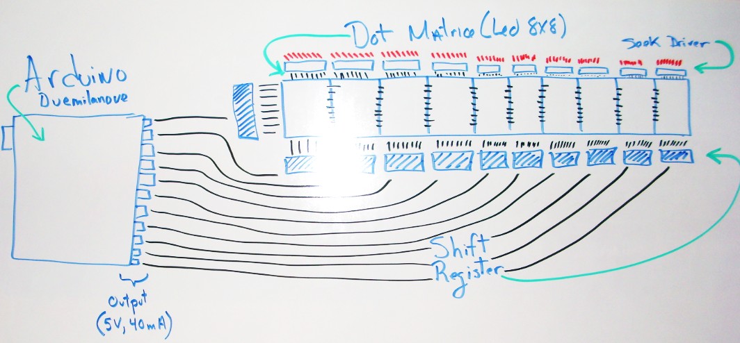
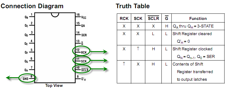
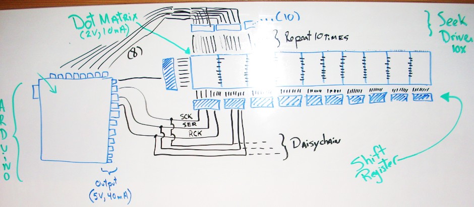
I have see in this website Instructables a way to do a LED scroll with Led DotMatrix. I have see them in Ebay with a PDF that show me some information about them here. My problem concern the Shift register and the use of what he uses : MIC2981 (drivers, or any other high current, high voltage drivers). I think he use the MIC2981 because it requires higher voltage... but I am not pretty sure to understand.

Can someone give me some hint about it and give me more information about doing this kind of project?

Thank you :)
By daok
#66410
FartingMonkey92 wrote:Have you had a look at how Sparkfun did theirs?

Have a glance over the schematics from these product pages:
LED Matrix - Serial Interface - Red/Green,LED Matrix - Serial Interface - Red/Green/Blue

That's how you do it with the fewest parts...
Any questions, shoot 'em this way... :wink:
Oh my God, I think I will love this website! Let me take a deeper look to your links. :) :) :) I will come back here to give you some news after :)
User avatar
By FartingMonkey92
#66411
Someone elses project, very similar to Sparkfun's schematics...
Relevant link - LED matrix projector
By daok
#66428
Alright,

So, I could buy those DotMatrix(10 for 25$) and connect them with the Aduino board (5v and 40 mA by output). The DotMatrix is Forward Voltage: 2V, Forward Current:5-10mA.

Since I plan to have these 10 DotMatrix side by side. I think I can have the 8 rows connected via 1 shift register to 1 outputs from the Arduino and have them connected together. For the columns, I have 8 columns x 10 DotMatrix, so I will need 10 ShiftRegister connected to the ArduinoBoard to the DotMatrix. Since all those DotMatrix require a lot of power, I will need something to sink the power from the led via 8 Sink Driver (like this project).

Here is a quick idea of all what I just said:

Image

I have problem to find how to connect the Sink Driver to the board? It's the red lines in the graphic above...How can I do that? :S
User avatar
By FartingMonkey92
#66429
First thing, that white board diagram is awesome... I wish i had a decent whiteboard.

Second thing, The shift registers only really require 3 lines for any amount you need for this project, you daisy chain them together...

Third thing, refering to the schematic on the Tinkerlog page, you would have 1 sink driver for each display, but simply parallel pins 1-8 together for all your sink drivers.

By the way, all the E-Bay links you have provided contain common-anode displays. We have been talking about how to drive common-cathode displays...

Extra choices:
But, there is another way to do this whole thing. You could use a TLC5920 from TI, one chip for two displays, of single colour... Nice. :wink:
Or you could use one of Maxim-ic's MAX696X series...

It just depends how complicated you want your circuit to be, i would start with one module, whatever you do and get it working, then make more.

...You got me wanting to make a few dotmatices now...
Last edited by FartingMonkey92 on Tue Feb 17, 2009 12:10 pm, edited 1 time in total.
By daok
#66434
FartingMonkey92 wrote:First thing, that white board diagram is awesome...

Second thing, The shift registers only really require 3 lines for any amount you need for this project, you daisy chain them together...

Third thing, refering to the schematic on the Tinkerlog page, you would have 1 sink driver for each display, but simply parallel pins 1-8 together for all your sink drivers.

But, there is another way to do this whole thing. You could use a TLC5920 from TI, one chip for two displays, of single colour... Nice. :wink:

Now i know how many displays you want, i'd go with a few TLC5920's... :D
:) I am learning a lot with you. Thanks.

So, the Shift Registercan use only 3 wires instead of the amount used in my diagram (11)? Here is a picture of the Shift Register and I have put in green the wire that I think you are talking about.

Image

Offertunatly, I do not understand how with only 3 wires (3 outputs from Arduino Board to the first Shift Register and daisy chain to other) I will be able to select with the code which led to open?

In your third point, you explain me to "simply parallel pins 1-8 together for all your sink drivers". I do not understand what you mean. You mean that I put all together all pins 1, than all pins 2, etc... but where do I plug them after that?
User avatar
By FartingMonkey92
#66435
Sorry, i was editing my post as you posted!
daok wrote:In your third point, you explain me to "simply parallel pins 1-8 together for all your sink drivers". I do not understand what you mean. You mean that I put all together all pins 1, than all pins 2, etc... but where do I plug them after that?
Yes, you would then plug the 8 pins into your Arduino.
User avatar
By FartingMonkey92
#66437
That's a nice/great offer ohararp, one i'd like too but i ain't a code guy. :(
For daok if you're still interested - Arduino - ShiftOut
By daok
#66439
:) Glad that you find the subject interesting :)

Well, I want to make it simple because I am really new to all this and I am trying to understand the most I can with this project.

You are talking about "common-anode displays" and "common-cathode displays" well for me anode is Positive side of the Led and Cathod is the Negative. I do not see why it does make change :P Is it because the Sunk Driver has a side? If yes, I really do not care to change of component :P The only thing I have really now is the Arduino Board and few resistor ;) Of course, I like those Ebay Dot Matrix because they are a LOT cheaper. What do you suggest?

Here is an update of the graphic of the wire :

Image

Do I start to understand :D
By daok
#66440
FartingMonkey92 wrote:That's a nice/great offer ohararp, one i'd like too but i ain't a code guy. :(
For daok if you're still interested - Arduino - ShiftOut
Thx for the link, I will read the whole article as soon as I can! I am a programmer so it won't be a problem for the code, it's really the electronic part that is a total maze for me :P
User avatar
By FartingMonkey92
#66441
You are right, for a single colour common-cathode/anode doesn't really matter except for pinout changes.
You're diagram is coming along well, you can erase the sink driver with the single line in the middle tho, it's not needed.

You will need to calculate the resistor values which would go between each shift register line and led module column. :wink:
daok wrote:I am a programmer so it won't be a problem for the code, it's really the electronic part that is a total maze for me
Complete opposite for me...
User avatar
By FartingMonkey92
#66446
I had another thought about the sink drivers, as long as you only used you're single colour LED's at 10ma max each, you could literally stack a chip onto another to increase the current handling.

10ma * 8 * 10 = 800ma

Would require only 2 sink drivers for the ten LED modules.

Or better, use 1 sink driver for every 2 LED modules, which will run cooler.

Just thought i'd add that. :wink:
By daok
#66451
Ok, few questions come in my minds.

First, you tell me that I can remove some wire in my diagram but I really do not see which one :(

For the 800ma, if led is 10ma max, I would have 8x8leds for a total of 64 leds x 10ma = 640ma x 10 Matrix = 6400ma isn't?

Each Sink Driver can handle 500ma I believe right (here is the spec). So in fact 6400/500 require me more than 10 :shock: I am confused :shock:
  • 1
  • 2
  • 3
  • 4
  • 5
  • 11