SparkFun Forums 

Where electronics enthusiasts find answers.

Discussions on the software and hardware for Atmel's STK standard.
By estranged
#71793
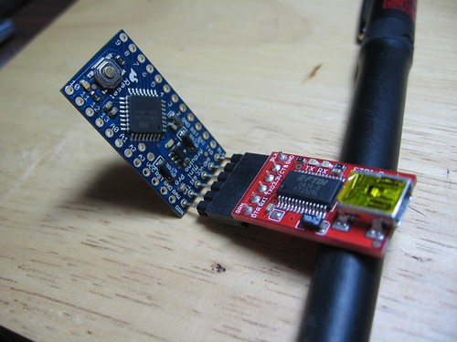
I just got my FTDI Breakout 3.3 today, and it doesn't seem to be recognized by my mac, nor power the pro mini.

I have the FTDI Drivers installed, I have successfully programmed a Duemilanove and Seeeduino on this same computer.

I'm using a Macbook Pro.

Plugging in a mini-usb to just the FTDI board alone results in flickering Tx Rx lights on the FTDI board.

Powering the Arduino Pro Mini with a battery yields the blinking pin 13 LED. Connecting the FTDI board to the Pro Mini stops the Tx Rx lights from flashing on the FTDI board, but the pin 13 LED does not flash on the pro mini.

At no time does a tty.usbserial-XXXXXX appear as does when I connect either the Seeeduino or Duemilanove.

Am I confused about the operation of the FTDI breakout board when it is not connected to anything, should it show up as a serial port still?

I am connecting pins from BLK <-> BLK and GRN <-> GRN.

Image

I'm stumped.
By bikeNomad
#72985
You should see the FTDI board appear as both /dev/tty.usbserial-xxxxxxxx and /dev/cu.usbserial-xxxxxxxx when you connect it (with or without a Mini attached).
Code: Select all
ls -l /dev/cu.*
You can do a loopback test by connecting the RXI (5) and TXO (4) pins of the FTDI board together.

I just did that on my Mac, and did this to test it:
Code: Select all
ls -l > /dev/cu.usbserial-A6007D0z & cat /dev/cu.usbserial-A6007D0z 
If you see output, your port is working.

I don't know whether the FTDI board will power the Mini, with nothing else connected, though (because you're feeding the output of the voltage regulator without having anything connected to its input). Had I not just hacked my FTDI 3.3V board to run at 5V, I'd try this experiment.

Have you checked the voltages on the Mini's serial pins? You should see 3.3V on the VCC (3) pin with respect to ground (1). And the TXO and RXI pins should both be around 3.3V when the two boards are connected together and the Mini is properly powered.

If you don't, you may want to try connecting pins 1-4 on JP6 (to provide power to the regulator input too).

Or you can attach a battery (>3.5V) to JP6/1 (and its ground to JP6/2) so that you're using the Mini's onboard 3.3V regulator to power the micro.
By estranged
#75915
Yeah nothing ever shows up in /dev, and the loopback trick fails. After several emails to sparkfun tech support with no response what so ever, I tossed the board in a junk pile and ordered an FTDI cable from adafruit. It seems to work great. I guess you just have to hope stuff works when you buy it here, because there isn't any support really.
By stevech
#75930
try calling them. I had an OK response to a DOA item.
By signal7
#76306
I wouldn't go off the deep end and say SFE doesn't support their products! My experience is very much the opposite. The forums don't get much love from the staff, but that doesn't mean you shouldn't call and ask for help.

Putting that aside for a moment, do you have another computer you can plug it into to try and verify proper operation? Heck - I'd even try a different cable if I had one just to be sure.
By vitcla
#76474
Are you sure you got a 3.3V Arduino Pro Mini? I was similarly angry before I realized that I tried to use a 3.3-Adapter for a 5V device. The worst thing is, that it works sometimes.

I suppose, your adapter works if you pimp pimp it like shown in the photo:

Image
By signal7
#76580
Ok - now, that's interesting. I have the FTDI FT232RL full breakout and noticed similar behavior as the OP when VCCIO is connected to 5V. For 5V operation, I simply left VCCIO disconnected. If you connect VCCIO to 5V, the device fails to be identified when connected to the USB bus. Your modifications appear to do something similar - which is to modify it for 3.3V operation which *does* work when it's connected to the host computer.

IIRC, this is contrary to the datasheet.