SparkFun Forums 

Where electronics enthusiasts find answers.

Have questions about a SparkFun product or board? This is the place to be.
By metaforest
#73063
An important consideration as you add more drivers....
If the code halts or something goes bad in the host, having a auto-blanking circuit that times out if the host doesn't twiddle it every so often...
When the host processor gets a reset you might want to apply that reset to the shift chain as well to blank the display when its not being driven.

Could be a simple as having the host keeping a capacitor charged(discharged) to keep the resets on the shift chain deasserted. If the host doesn't service the auto-blank the cap's charge dies off(or fills up) and the shifter chain resets get asserted. The choice as to wether to charge the cap or discharge it would be dependent on what the assert for the shifter chain looks like... you might need a transistor/fet to actually drive the resets with it's Base/Gate driven from the RC. done right it should only add a few of resistors, two decent sized caps, and a transistor/fet.

Just a thought.... That could save you blown chips and LEDs.
By daok
#73064
metaforest wrote:An important consideration as you add more drivers....
If the code halts or something goes bad in the host, having a auto-blanking circuit that times out if the host doesn't twiddle it every so often...
When the host processor gets a reset you might want to apply that reset to the shift chain as well to blank the display when its not being driven.

Could be a simple as having the host keeping a capacitor charged(discharged) to keep the resets on the shift chain deasserted. If the host doesn't service the auto-blank the cap's charge dies off(or fills up) and the shifter chain resets get asserted. The choice as to wether to charge the cap or discharge it would be dependent on what the assert for the shifter chain looks like... you might need a transistor/fet to actually drive the resets with it's Base/Gate driven from the RC. done right it should only add a few of resistors, two decent sized caps, and a transistor/fet.

Just a thought.... That could save you blown chips and LEDs.
Alright, where in the schema goes the Capacitor and the transistor? Before every Sink Driver? What is RC.. for me it's Radio Controller :o I

The capacitor hold current (from what I know) and I do not understand why it would be important in a "reset"? In my point of view (newby point of view) if I reset the controller board, the current just decimate naturally isn't?

I think I need some information to understand :roll:
By metaforest
#73071
** THIS HAS BEEN CHANGED ** I had a polaroty error due to misunderstanding how the /G line on the shift register worked.

IF the CPU halts unexpectedly you can have a case where one or more of the driver control lines are asserted potentially over-heating the driver chip and some LEDs because they are seeing DC rather than the multiplexed drive. The auto-blank prevents that by providing a timeout if the CPU fails to update the autoblank input regularly.

ok as for the details of the autoblank idea, a picture is worth 1000 words:

Image

The idea is that when the keep_alive line is pulsed high regularly the fet stays on, holding the /G lines on the shift registers low. If the pulses dont appear often enough, OR the autoblank line is held high the caps discharrge charge and the fet stops passing current. This will pull the /gate line high, turning off the shift chain's outputs.

Now I know I came in a little late on this project, but something was bugging me about all the driver lines going to the host CPU... so I came up with a solution that allows an extra shift register to hold the driver selection, thus freeing all those precious lines on the CPU for other tasks.


See the PDF hosted here on my server:
http://www.meta-forest.net/10x8matrix.pdf

let me know what you all think on both ideas.

Cheers!

*** EXTENSIVE EDIT ABOVE ***
Last edited by metaforest on Tue May 19, 2009 6:44 pm, edited 1 time in total.
User avatar
By FartingMonkey92
#73080
metaforest wrote:"Now I know I came in a little late on this project, but something was bugging me about all the driver lines going to the host CPU... so I came up with a solution that allows an extra shift register to hold the driver selection, thus freeing all those precious lines on the CPU for other tasks."
Good ideas. I believe daok is already using another shift register to control the ULN's, it just isn't in the same chain as the others...

Anyway, good thinking on the "keep-alive" type thing.
By daok
#73082
Oh my! I think I will need to Google some of the concept you just kindly explicate me to really understand well. In my words, I understand that if the MicroController hang-up by accident that the current could blow out something so I need something that will hold the current.

In the PDF file I see that only the last 3 SinkDriver has "Gate" (I guess it's what you are talking about with the Alternate Blank), why only those 3 have this mechanism? In this post I had a schematic of what I have, where do you suggest me to use your configuration? I think it's between the Microcontroller and the SinkDriver that are daisy chained?

By the way, the Shift Register for the Columns are daisy chain together and I have an other chain (that start from the MicroController) for the SinkDriver (I will daisy chain the SinkDriver together every four LedMatrix).

Thank you for your answer, I will read it again to try to understand it more because I am still confuse. :roll:
By metaforest
#73097
daok wrote:Oh my! I think I will need to Google some of the concept you just kindly explicate me to really understand well. In my words, I understand that if the MicroController hang-up by accident that the current could blow out something so I need something that will hold the current.

In the PDF file I see that only the last 3 SinkDriver has "Gate" (I guess it's what you are talking about with the Alternate Blank), why only those 3 have this mechanism?

By the way, the Shift Register for the Columns are daisy chain together and I have an other chain (that start from the MicroController) for the SinkDriver (I will daisy chain the SinkDriver together every four LedMatrix).
The way it works is that if /GATE asserts it turns off the current flowing from ALL source drivers (columns). FM92 correctly calls the circuit that controls the /GATE signal a "Keep-Alive" in my late-night fog I called it auto-blank.

The number of row drivers can be reduced from my drawing if needed ...

The three shift registers turned upside-down is a visual convenience to keep them all on the same page, and does not reflect their function or configuration. The last shift register in the chain drives the ROW drivers. I chose to interleave the ROW lines on the drivers to evenly distribute current... it is not necessary to do this, but as you will learn, every designer has their own little ways they like to approach a layout, and only change the circuit in very subtle ways, without really changing it's function.

In software we do the same thing... preferring some idiomatic expressions over others, sometimes only for aesthetic reasons....

In the auto-blank (keep-alive) circuit, R1 may need to be smaller, say 33K to 50K. It's only purpose is to increase the discharge rate of C1. Since C1 acts as a DC blocking capacitor it needs to be charged so that it will pass the HIGH active KEE_ALIVE signal from the host. R2 will not discharge C1 significantly when KEEP_ALIVE is floating (tri-state). C1 and C2 to are sized such that when KEEP_ALIVE is held HIGH, enough current flows out of C2 to reset the circuit before C1 charges enough to block current. R1 must be large enough to prevent the charge of C2 in the case where KEEP_ALIVE is held HIGH indefinitely due to the host failing to de-assert. If this were not so then the host could hold KEEP_ALIVE HIGH and /GATE would never assert.

R2 controls the discharge rate of C2. Increasing the resistor value will increase the time it takes until Q1 stops passing current. The limit is that R2 must always be a 1/3 to 1/2 the size of R1 to prevent R1 from sourcing too much current by itself when C1 completes discharging. R3 is used to hold the /GATE signal high when Q1 is not passing current.
Last edited by metaforest on Tue May 19, 2009 6:49 pm, edited 1 time in total.
By daok
#73113
Wow Thank you for all the information. I will have to read all what your wrote few times just to be sure to understand.

So, before trying to solder anything I have two new tasks

1) Find where to put all the keep-alive stuff.
2) Find what value to use in the keep-alive.

I will try to post something before thursday.

Very impressive answer Metaforest, thank
By daok
#73117
daok wrote:Wow Thank you for all the information. I will have to read all what your wrote few times just to be sure to understand.

So, before trying to solder anything I have two new tasks

1) Find where to put all the keep-alive stuff.
2) Find what value to use in the keep-alive.

I will try to post something before thursday.

Very impressive answer Metaforest, thank
I have re-check your PDF and in fact I see the gate in all ShiftRegister...
Here is a snapshot of the PDF and at the right side is the schema from the documentation. I have put some info on it...

Image

So, the "gate" of the keep-alive should replace the red wire (from the 5v) right?
By metaforest
#73120
So, the "gate" of the keep-alive should replace the red wire (from the 5v) right?

I have made an error in the keep-alive.

The /G line must be held low to allow QA-QH to be active. When /G is high the shift register outputs will be in TRI-state mode.

The correction is to swap the locations of C2 and R2. And to change the polarity of the keep-alive signal from the host CPU to HIGH.

The effect here is opposite the previous layout. Without proper input from the CPU, the FET will gradually stop passing current causing /GATE to go high. When the CPU toggles the KEEP_ALIVE input from TRI-state to HIGH regularly the fet will maintain current flow, thus holding /GATE in the LOW-active state.

I will correct my drawing in the earlier post to reflect this change.

The /GATE signal from the fet will replace the GROUND you show at the /G signal. No change should be made to the /RCLR line. You show it tied to +5V and this is correct for your application.

**EDIT** I have completed the update to the drawing AND to the rest of the earlier discussion on this topic.
By daok
#73150
The PDF link and the image link are broken I think. I will have to read carefully your change today. I'll post back with some questions later. Thanks for the update.
By metaforest
#73331
daok wrote:The PDF link and the image link are broken I think. I will have to read carefully your change today. I'll post back with some questions later. Thanks for the update.
There is something going on with the PDF, but I was able to download it. It will not load in my browser no idea why... it did after I posted it.

The jpg seems to be fine. It loaded correctly over here.
By daok
#73360
Alright I think I get it more and more.

The thing I want to be sure, I see that the major change will be at the pin13 (/G) of the Shift Register. Do I have to do it to all (like your PDF seem to show me) or only the shift register that is used with the Sink Driver?

Question 2 concerne the choice of the Transistor and the ohm for the resistance. You say that "R2 must always be a 1/3 to 1/2 the size of R1" but in the graphic you show, R2 is 1/10... why?

For the transistor, I have read the datasheet and it say it's 16 ohm (Rds) and Vds at 240v and Vgs at 0.8 to 2V. I do not understand why it will works with the stuff I have already, can you give me some explication please?
By daok
#73519
I have some other question about how everything will react when all will be setup up together. I got this new question by reading this post.

The ShiftRegister in the DataSheet indicate a Power Dissipation of 500 mw. The LedMatrix has a Power Dissipation of 100 mw (20mA * 5v). So, I will have problem when daisy chaining more than 5 Shift Register?

metaforest can you answer my latest post (22 may 2009) when you have time, I would like to understand :oops:
By daok
#74003
daok wrote:Alright I think I get it more and more.

The thing I want to be sure, I see that the major change will be at the pin13 (/G) of the Shift Register. Do I have to do it to all (like your PDF seem to show me) or only the shift register that is used with the Sink Driver?

Question 2 concerne the choice of the Transistor and the ohm for the resistance. You say that "R2 must always be a 1/3 to 1/2 the size of R1" but in the graphic you show, R2 is 1/10... why?

For the transistor, I have read the datasheet and it say it's 16 ohm (Rds) and Vds at 240v and Vgs at 0.8 to 2V. I do not understand why it will works with the stuff I have already, can you give me some explication please?
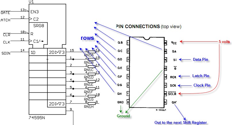
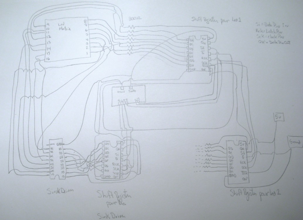
I still doesn't have the answer to those questions but I have remake the complete graphic for the schematic here.

The code that work is here:
Code: Select all

#ifndef __PATTERN_H
#define __PATTERN_H


#include <avr/pgmspace.h>

typedef prog_uchar patternp[8]; // stored in progmem
void scrollString(const char * s, unsigned int gap);
const patternp * getPattern(unsigned char c);

const patternp PATTERN_BLANK PROGMEM = {
   0 ,
   0 ,
   0 ,
   0 ,
   0 ,
   0 , 
   0 
};
const patternp PATTERN_SOLID PROGMEM = {
  0b11111111,
  0b11111111,
  0b11111111,
  0b11111111,
  0b11111111,
  0b11111111,
  0b11111111,
  0b11111111
};
const patternp PATTERN_A PROGMEM = {
  0b11110000,
  0b10010000,
  0b10010000,
  0b11110000,
  0b10010000,
  0b10010000,
  0b10010000,
  0b10010000
};
const patternp PATTERN_B PROGMEM = {
  0b11100000,
  0b10010000,
  0b10010000,
  0b11100000,
  0b10010000,
  0b10010000,
  0b10010000,
  0b11100000
};
const patternp PATTERN_C PROGMEM = {
  0b11110000,
  0b10010000,
  0b10000000,
  0b10000000,
  0b10000000,
  0b10000000,
  0b10010000,
  0b11110000
};
const patternp PATTERN_D PROGMEM = {
  0b11100000,
  0b10010000,
  0b10010000,
  0b10010000,
  0b10010000,
  0b10010000,
  0b10010000,
  0b11100000
};
const patternp PATTERN_E PROGMEM = {
  0b11110000,
  0b10000000,
  0b10000000,
  0b11100000,
  0b10000000,
  0b10000000,
  0b10000000,
  0b11110000
};
const patternp PATTERN_F PROGMEM = {
  0b11110000,
  0b10000000,
  0b10000000,
  0b10000000,
  0b11100000,
  0b10000000,
  0b10000000,
  0b10000000
};
const patternp PATTERN_G PROGMEM = {
  0b11110000,
  0b10000000,
  0b10000000,
  0b10000000,
  0b10110000,
  0b10010000,
  0b10010000,
  0b11110000
};
const patternp PATTERN_H PROGMEM = {
  0b10010000,
  0b10010000,
  0b10010000,
  0b11110000,
  0b10010000,
  0b10010000,
  0b10010000,
  0b10010000
};
const patternp PATTERN_I PROGMEM = {
  0b01110000,
  0b00100000,
  0b00100000,
  0b00100000,
  0b00100000,
  0b00100000,
  0b00100000,
  0b01110000
};
const patternp PATTERN_J PROGMEM = {
  0b01110000,
  0b00100000,
  0b00100000,
  0b00100000,
  0b00100000,
  0b10100000,
  0b10100000,
  0b11100000
};
const patternp PATTERN_K PROGMEM = {
  0b10010000,
  0b10010000,
  0b10100000,
  0b11000000,
  0b10100000,
  0b10010000,
  0b10010000,
  0b10010000
};
const patternp PATTERN_L PROGMEM = {
  0b10000000,
  0b10000000,
  0b10000000,
  0b10000000,
  0b10000000,
  0b10000000,
  0b10000000,
  0b11110000
};
const patternp PATTERN_M PROGMEM = {
  0b10001000,
  0b11011000,
  0b10101000,
  0b10001000,
  0b10001000,
  0b10001000,
  0b10001000,
  0b10001000
};
const patternp PATTERN_N PROGMEM = {
  0b10001000,
  0b11001000,
  0b10101000,
  0b10101000,
  0b10011000,
  0b10011000,
  0b10001000,
  0b10001000
};
const patternp PATTERN_O PROGMEM = {
  0b01100000,
  0b10010000,
  0b10010000,
  0b10010000,
  0b10010000,
  0b10010000,
  0b10010000,
  0b01100000
};
const patternp PATTERN_P PROGMEM = {
  0b11110000,
  0b10010000,
  0b10010000,
  0b11110000,
  0b10000000,
  0b10000000,
  0b10000000,
  0b10000000
};
const patternp PATTERN_Q PROGMEM = {
  0b01100000,
  0b10010000,
  0b10010000,
  0b10010000,
  0b10010000,
  0b10010000,
  0b10100000,
  0b01010000
};
const patternp PATTERN_R PROGMEM = {
  0b11100000,
  0b10010000,
  0b10010000,
  0b10100000,
  0b11000000,
  0b10100000,
  0b10010000,
  0b10010000
};
const patternp PATTERN_S PROGMEM = {
  0b01100000,
  0b10010000,
  0b10000000,
  0b01100000,
  0b00010000,
  0b00010000,
  0b00010000,
  0b11100000
};
const patternp PATTERN_T PROGMEM = {
  0b11111000,
  0b00100000,
  0b00100000,
  0b00100000,
  0b00100000,
  0b00100000,
  0b00100000,
  0b00100000
};
const patternp PATTERN_U PROGMEM = {
  0b10010000,
  0b10010000,
  0b10010000,
  0b10010000,
  0b10010000,
  0b10010000,
  0b10010000,
  0b11110000
};
const patternp PATTERN_V PROGMEM = {
  0b10010000,
  0b10010000,
  0b10010000,
  0b10010000,
  0b10010000,
  0b10010000,
  0b01100000,
  0b00100000
};
const patternp PATTERN_W PROGMEM = {
  0b10001000,
  0b10001000,
  0b10001000,
  0b10101000,
  0b10101000,
  0b10101000,
  0b10101000,
  0b01010000
};
const patternp PATTERN_X PROGMEM = {
  0b10010000,
  0b10010000,
  0b01100000,
  0b01100000,
  0b01100000,
  0b10010000,
  0b10010000,
  0b10010000
};
const patternp PATTERN_Y PROGMEM = {
  0b10010000,
  0b10010000,
  0b10010000,
  0b10010000,
  0b01100000,
  0b01000000,
  0b01000000,
  0b01000000
};
const patternp PATTERN_Z PROGMEM = {
  0b11110000,
  0b00010000,
  0b00010000,
  0b00100000,
  0b00100000,
  0b01000000,
  0b10000000,
  0b11110000
};
const patternp PATTERN_1 PROGMEM = {
  0b00100000,
  0b01100000,
  0b10100000,
  0b00100000,
  0b00100000,
  0b00100000,
  0b00100000,
  0b11110000
};
const patternp PATTERN_2 PROGMEM = {
  0b01100000,
  0b10010000,
  0b00010000,
  0b01100000,
  0b10000000,
  0b10000000,
  0b10000000,
  0b11110000
};
const patternp PATTERN_3 PROGMEM = {
  0b11100000,
  0b00010000,
  0b00100000,
  0b01000000,
  0b10000000,
  0b01100000,
  0b00100000,
  0b11000000
};
const patternp PATTERN_4 PROGMEM = {
  0b10010000,
  0b10010000,
  0b10010000,
  0b11110000,
  0b00010000,
  0b00010000,
  0b00010000,
  0b00010000
};
const patternp PATTERN_5 PROGMEM = {
  0b11110000,
  0b10000000,
  0b10000000,
  0b11100000,
  0b00010000,
  0b00010000,
  0b00010000,
  0b11100000
};
const patternp PATTERN_6 PROGMEM = {
  0b01100000,
  0b10010000,
  0b10000000,
  0b10000000,
  0b11100000,
  0b10010000,
  0b10010000,
  0b01100000
};
const patternp PATTERN_7 PROGMEM = {
  0b11110000,
  0b00010000,
  0b00010000,
  0b00100000,
  0b01000000,
  0b01000000,
  0b01000000,
  0b01000000
};
const patternp PATTERN_8 PROGMEM = {
  0b01100000,
  0b10010000,
  0b10010000,
  0b01100000,
  0b10010000,
  0b10010000,
  0b10010000,
  0b01100000
};
const patternp PATTERN_9 PROGMEM = {
  0b01110000,
  0b10010000,
  0b10010000,
  0b01110000,
  0b00010000,
  0b00010000,
  0b00010000,
  0b00010000
};
const patternp PATTERN_0 PROGMEM = {
  0b01100000,
  0b10010000,
  0b10110000,
  0b11010000,
  0b11010000,
  0b10010000,
  0b10010000,
  0b01100000
};
const patternp PATTERN_AT PROGMEM = {
  0b01110000,
  0b10001000,
  0b10101000,
  0b10101000,
  0b10101000,
  0b10101000,
  0b10011000,
  0b01110000
};
const patternp PATTERN_PLUS PROGMEM = {
  0b00000000,
  0b00000000,
  0b00100000,
  0b00100000,
  0b11111000,
  0b00100000,
  0b00100000,
  0b00000000
};
const patternp PATTERN_MINUS PROGMEM = {
  0b00000000,
  0b00000000,
  0b00000000,
  0b00000000,
  0b11111000,
  0b00000000,
  0b00000000,
  0b00000000
};
const patternp PATTERN_EQUAL PROGMEM = {
  0b00000000,
  0b00000000,
  0b00000000,
  0b11111000,
  0b00000000,
  0b11111000,
  0b00000000,
  0b00000000
};
const patternp PATTERN_LESS PROGMEM = {
  0b00000000,
  0b00010000,
  0b00100000,
  0b01000000,
  0b10000000,
  0b01000000,
  0b00100000,
  0b00010000
};
const patternp PATTERN_GREATER PROGMEM = {
  0b00000000,
  0b10000000,
  0b01000000,
  0b00100000,
  0b00010000,
  0b00100000,
  0b01000000,
  0b10000000
};
const patternp PATTERN_PARENTHESIS_LEFT PROGMEM = {
  0b00100000,
  0b01000000,
  0b01000000,
  0b10000000,
  0b10000000,
  0b01000000,
  0b01000000,
  0b00100000
};
const patternp PATTERN_PARENTHESIS_RIGHT PROGMEM = {
  0b00100000,
  0b00010000,
  0b00010000,
  0b00001000,
  0b00001000,
  0b00010000,
  0b00010000,
  0b00100000
};
#endif


Here is the code for the MatrixMatin.pde
Code: Select all
#include "Pattern.h"
#include <string.h>
#include <WProgram.h>

//For the timer (interrupt)
#include <avr/io.h>
#include <avr/interrupt.h>


#define NUMBER_COL_PER_MATRIX 8
#define NUMBER_ROW_PER_MATRIX 8
#define NUMBER_LED_MATRIX 2
#define LETTER_USE_X_COLUMN 5

int latchPin = 8;
int clockPin = 12;
int dataPin = 11;
int latchPin_sink = 5;
int clockPin_sink = 6;
int dataPin_sink = 7;
volatile boolean moveLedForward = true;
volatile uint8_t countTimer;
volatile uint8_t numberOfLedFowarded = 0;

void setupTimer()
{
 
   TCCR2A = 0;
   TCCR2B|=(1<<CS20)|(1<<CS21)|(1<<CS22);  // Prescaler = FCPU/1024
   TIMSK2=(1<<TOIE2);   		//Enable Overflow Interrupt Enable
   TCNT2=0;  					//Initialize Counter
   //TCCR2 &= ~((1<<WGM21) | (1<<WGM20));   // turn off WGM21 and WGM20 bits
   countTimer=0;   				//Initialize our varriable
   sei();						//Enable Global Interrupts
}
 
ISR(TIMER2_OVF_vect)
{
   //This is the interrupt service routine for TIMER0 OVERFLOW Interrupt.
   //CPU automatically call this when TIMER0 overflows.

   //Increment our variable
   countTimer++;
   //Serial.println(countTimer,DEC);
   if(countTimer==10)//61 = 1 secondes
   {
        countTimer=0;
		moveLedForward = true;
   }
} 

void setup() {
	//set pins to output because they are addressed in the main loop
	pinMode(latchPin, OUTPUT);
	pinMode(latchPin_sink, OUTPUT);
	pinMode(clockPin, OUTPUT);
	pinMode(clockPin_sink, OUTPUT);
	pinMode(dataPin, OUTPUT);
	pinMode(dataPin_sink, OUTPUT);
	Serial.begin(9600);

	//Reset Sink
	digitalWrite(latchPin_sink, 0);
	shiftOut(dataPin_sink, clockPin_sink, 0xff); 
	digitalWrite(latchPin_sink, 1);
	
	setupTimer();
	
	blinkAll(2,500); 
}

void loop() 
{
  scrollString("1+2=4-1>0<10", 2);
  delay(1000);
}


void scrollString(const char *s, unsigned int gap)
{
  int iLetter = 0;
  int numberTotalLetter = strlen(s);
  Serial.println(numberTotalLetter);
  boolean lastLetterHasBeenSent = false;
  unsigned int totalNumberColumn = NUMBER_LED_MATRIX * NUMBER_COL_PER_MATRIX;
  byte dataArray[NUMBER_LED_MATRIX][NUMBER_ROW_PER_MATRIX];
  uint8_t rowPatternData[NUMBER_ROW_PER_MATRIX];
		
  //Put 0 to all
  for(int iLedMatrix = 1;iLedMatrix<=NUMBER_LED_MATRIX;iLedMatrix++)
  {
    for(int iRow = 0 ; iRow < NUMBER_ROW_PER_MATRIX ; iRow++)
    {
      dataArray[iLedMatrix-1][iRow] = 0;
    }
  }
  
  //Serial.print("scrollString: ");
  //Serial.println(*s);
  
	while (s[iLetter] || lastLetterHasBeenSent)//For each letter to display
	{
    //Serial.print("Letter: ");
    //Serial.println(s[iLetter]);
	    if(moveLedForward)
	    {
			//Serial.println("Moving Forward");
			if(numberOfLedFowarded==0)//Only at the beginning of a sequence
			{
				//Get Pattern from the FLASH memory
				const patternp *bufferPattern = getPattern(s[iLetter]);   
				//debugPrintArrayPattern(*bufferPattern);
				for(int iRow = 0; iRow<NUMBER_ROW_PER_MATRIX; iRow++)
				{  
					rowPatternData[iRow]=pgm_read_byte( &((*bufferPattern)[iRow]) );
				}
			}

			//For each Led Matrix, write down to the array what should be display
			for(int iLedMatrix = (NUMBER_LED_MATRIX-1);iLedMatrix>=0;iLedMatrix--)
			{
				if(iLedMatrix>0)//Not the last one
				{
				  //Serial.println("Not last Matrix");
				  //Shift the screen data to the left 1 led
				  for(int iRow = 0 ; iRow < NUMBER_ROW_PER_MATRIX ; iRow++)
				  {
					dataArray[iLedMatrix][iRow] = dataArray[iLedMatrix][iRow] << 1;
					dataArray[iLedMatrix][iRow] |=  ((dataArray[iLedMatrix-1][iRow] & (1<<7)))>>7;//Take the first led of the matrix of the right side
				  }
				}
				else//We are at the last, take from the buffer
				{
					// Led Matrix 0 (Max Right)
					if(lastLetterHasBeenSent) //All letters of the message has been sent to LedMatrix, No need to take stuff from buffer
					{
						for(int iRow = 0 ; iRow < NUMBER_ROW_PER_MATRIX ; iRow++)
						{
							dataArray[iLedMatrix][iRow] = dataArray[iLedMatrix][iRow] << 1;
							dataArray[iLedMatrix][iRow] |=  ( ((byte)0) & (1<<7) )>>7;
						}
					}
					else
					{
						//Shift the screen data to the left 1 led
						for(int iRow = 0 ; iRow < NUMBER_ROW_PER_MATRIX ; iRow++)
						{
							if(numberOfLedFowarded==0 & iLetter==0)//Start moving led sequence
							{
								dataArray[iLedMatrix][iRow] =  (((byte)rowPatternData[iRow]) & (1<<7))>>7;
							}
							else
							{
								dataArray[iLedMatrix][iRow] = dataArray[iLedMatrix][iRow] << 1;
								dataArray[iLedMatrix][iRow] |=  (((byte)rowPatternData[iRow]) & (1<<7))>>7;//Take the first led of the next matrix for the last led of the current
							}
							/*Serial.print("Byte Pattern for Row ");
									Serial.print(iRow);
									Serial.print(" is ");
									printbyte((byte)rowPatternData[iRow]);
									Serial.println();
							 
									Serial.print("Byte screen LED 0 for Row ");
									Serial.print(iRow);
									Serial.print(" is ");
									printbyte(dataArray[iLedMatrix][iRow]);
									Serial.println();
								   */
							rowPatternData[iRow] = rowPatternData[iRow]<<1;//Move the pattern
						}
					}
				}
			//debugPrintArray(dataArray[iLedMatrix]);
			}

			moveLedForward = false;//Wait interrupt to make it true;
			numberOfLedFowarded++;
			//if(numberOfLedFowarded==NUMBER_COL_PER_MATRIX+gap)
			if(numberOfLedFowarded==LETTER_USE_X_COLUMN+gap)
			{
				iLetter++;
				numberOfLedFowarded=0;
			}
	    }//Move forward all led

		//Serial.println("Print array to screen");
		//For each Led Matrix, take the data from the array to the led
		
		for (int row = 0; row < 8; row++) 
		{
			for(int iLedMatrix = 0;iLedMatrix<NUMBER_LED_MATRIX;iLedMatrix++)
			{
				//Erase the current row data by removing the current
				digitalWrite(latchPin_sink, 0);
				shiftOut(dataPin_sink, clockPin_sink, (0<<(row))); 
				digitalWrite(latchPin_sink, 1);
				  
				//Write the data we want in the rows
				digitalWrite(latchPin, 0);
				shiftOut(dataPin, clockPin, dataArray[iLedMatrix][row]);  
			}
			digitalWrite(latchPin, 1);
			
			for(int iLedMatrix = 0;iLedMatrix<NUMBER_LED_MATRIX;iLedMatrix++)
			{
				//Activate the colums to write the rows data
				digitalWrite(latchPin_sink, 0);
				shiftOut(dataPin_sink, clockPin_sink, (1<<row)); 
				digitalWrite(latchPin_sink, 1);
			}
		}  
		
		if(!lastLetterHasBeenSent)//We haven't display all letter yet
		{
			if(s[iLetter]==NULL)
			{
				lastLetterHasBeenSent = true;
			}
		}
		else//All letters has been displayed, still need to move them all from right to left
		{
			if(iLetter >= numberTotalLetter+NUMBER_LED_MATRIX)//It's over, all letter has been moved from right to left
			{
				//Need condition to stop everything because all letters has been sent and has moved from right to left completly
				lastLetterHasBeenSent = false;
			}
		}

    }//Each letters
    
}

void debugPrintArray(byte dataArray[NUMBER_ROW_PER_MATRIX])
{
  Serial.println("-----Array below------");
  for(int iRow = 0;iRow<NUMBER_ROW_PER_MATRIX;iRow++)
  {
    printbyte(dataArray[iRow]);
    Serial.println();
  }
}
void debugPrintArrayPattern(const patternp dataArray)
{
  Serial.println("-----Pattern below------");
  uint8_t rowPatternData[NUMBER_ROW_PER_MATRIX];
  
  for(int iRow = 0;iRow<NUMBER_ROW_PER_MATRIX;iRow++)
  {
    rowPatternData[iRow]=pgm_read_byte( &dataArray[iRow] );
    printbyte((byte)rowPatternData[iRow]);
    Serial.println();
  }
}  
void printbyte(byte b)
{
  for(int i = 1 ; i <= 8 ; i++)
  {
    Serial.print( (b &  (1<<8-i)) == (1<<8-i)?"1":"0");
  }
}

//This is the way to write to the shift register. My DataOut represent the Write (1) or not (0) to the shift register.
void shiftOut(int myDataPin, int myClockPin, byte myDataOut) 
{
  for (int i=0; i<8; i++)  
  {
    digitalWrite(myClockPin, 0);

    if ( myDataOut & (1<<i) ) {
      digitalWrite(myDataPin, 1);
    }else {	
      digitalWrite(myDataPin, 0);
    }
    digitalWrite(myClockPin, 1);
  }
}


//blinks the whole register based on the number of times you want to 
//blink "n" and the pause between them "d"
//starts with a moment of darkness to make sure the first blink
//has its full visual effect.
void blinkAll(int n, int d) {
  digitalWrite(latchPin, 0);
  shiftOut(dataPin, clockPin, 0);
  digitalWrite(latchPin, 1);
  delay(200);
  for (int x = 0; x < n; x++) {
    digitalWrite(latchPin, 0);
    shiftOut(dataPin, clockPin, 255);
    digitalWrite(latchPin, 1);
    delay(d);
    digitalWrite(latchPin, 0);
    shiftOut(dataPin, clockPin, 0);
    digitalWrite(latchPin, 1);
    delay(d);
  }
}


const patternp * getPattern(unsigned char c)
{
  switch (c)
  {
    case 'A':
		return &PATTERN_A;
	case 'B':
		return &PATTERN_B;
	case 'C':
		return &PATTERN_C;
	case 'D':
		return &PATTERN_D;
	case 'E':
		return &PATTERN_E;
	case 'F':
		return &PATTERN_F;
	case 'G':
		return &PATTERN_G;
	case 'H':
		return &PATTERN_H;
	case 'I':
		return &PATTERN_I;
	case 'J':
		return &PATTERN_J;
	case 'K':
		return &PATTERN_K;
	case 'L':
		return &PATTERN_L;
	case 'M':
		return &PATTERN_M;
	case 'N':
		return &PATTERN_N;
	case 'O':
		return &PATTERN_O;
	case 'P':
		return &PATTERN_P;
	case 'Q':
		return &PATTERN_Q;
	case 'R':
		return &PATTERN_R;
	case 'S':
		return &PATTERN_S;
	case 'T':
		return &PATTERN_T;
	case 'U':
		return &PATTERN_U;
	case 'V':
		return &PATTERN_V;
	case 'W':
		return &PATTERN_W;
	case 'X':
		return &PATTERN_X;
	case 'Y':
		return &PATTERN_Y;
	case 'Z':
		return &PATTERN_Z;
	case '0':
		return &PATTERN_0;
    case '1':
		return &PATTERN_1;
    case '2':
		return &PATTERN_2;
	case '3':
		return &PATTERN_3;
	case '4':
		return &PATTERN_4;
	case '5':
		return &PATTERN_5;
	case '6':
		return &PATTERN_6;
	case '7':
		return &PATTERN_7;
	case '8':
		return &PATTERN_8;
	case '9':
		return &PATTERN_9;
	case '@':
		return &PATTERN_AT;
	case '+':
		return &PATTERN_PLUS;
	case '-':
		return &PATTERN_MINUS;
	case '=':
		return &PATTERN_EQUAL;
	case '>':
		return &PATTERN_GREATER;
	case '<':
		return &PATTERN_LESS;
	case '(':
		return &PATTERN_PARENTHESIS_LEFT;
	case ')':
		return &PATTERN_PARENTHESIS_RIGHT;
	case ' ':
		return &PATTERN_BLANK;
    default:
      return &PATTERN_BLANK;
  }
}


Hope this can help other people.
By davos1
#74213
I am very interested in making my own LED matrix. I have read all the posts here, and purchased 5x74HC595 and 2xULN2803A from eBay and waiting for them to arrive. Meanwhile, I have written a program to generate code for a LED matrix. There are 2 programs. 1 generates hex code. Eg.
Code: Select all
0x08 //00001000
0x08 //00001000
0x38 //00111000
0x20 //00100000
0x20 //00100000
0xE0 //11100000
0x80 //10000000
0x80 //10000000
The other program writes it in binary. Eg.
Code: Select all
0b00000100
0b00001100
0b00001000
0b00111000
0b00100000
0b11100000
0b10000000
0b10000000
You can set the number of columns and rows. It also accepts command line parametres.
row[n] - It sets the number of rows
col[n] - It sets the number of columns
nocomm - Disables the comment of bits in the Hex version
Code: Select all
LEDcodegenHex.exe row8 col20
That will set it to 8 rows and 20 columns. The program defaults to 8 rows and 8 columns.

Screenshot (hex version):
Image
Download link: http://www.mediafire.com/?wmmzw5zngom

NOTE: The program is written in VB and you need the 3.5 NET framework to run it. Hope this program helps someone! :)
  • 1
  • 7
  • 8
  • 9
  • 10
  • 11