SparkFun Forums 

Where electronics enthusiasts find answers.

Have questions about a SparkFun product or board? This is the place to be.
By Adenosine
#94741
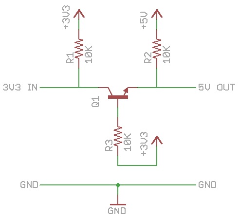
I'm planning to use something which will send 3.3v high/low signals to an Arduino, and I was wondering if connecting the 3.3v to the gate of a transistor (with both devices on a common ground) would allow 5v out to be read on an Arduino as high?
By MichaelN
#94742
An Arduino running on 5V will accept a 3.3V signal as a valid logic "high" signal, so you don't actually need any interface circuitry (have a look at the datasheet for the microcontroller used).

If you really want to use a transistor, the following circuit will do what you want, and will also provide some protection for the Arduino. Rpullup and Rbase are normally between 10K and 100K; the values aren't critical.
Image
By Adenosine
#94786
MichaelN wrote:An Arduino running on 5V will accept a 3.3V signal as a valid logic "high" signal, so you don't actually need any interface circuitry (have a look at the datasheet for the microcontroller used).

If you really want to use a transistor, the following circuit will do what you want, and will also provide some protection for the Arduino. Rpullup and Rbase are normally between 10K and 100K; the values aren't critical.
Image
Tested it out, and it works, but how can I hook it up so the signal is sent HIGH when it is pressed and LOW when not pressed? It currently works in the opposite.
By Adenosine
#94826
markaren1 wrote:Before you get too stuck into solution, what is the problem ?

What are you trying to interface to/from ?

-mark
I paid about $5 for a remote controlled car and it outputs to 3.0v, and works at the 3.3v so I'm using that as a cheap remote controller system. I set up the diodes in a way where it will output to this wire if pressing forward and a different wire if reverse. Same concept for L/R so I have 4 buttons.
By waltr
#94832
Adenosine wrote:
waltr wrote:Add a second transistor to re-invert the logic.
Could you explain what that means? I'm still new to all these electronics terms and stuff.
In the schematic above +3V on the input rises the transistor's base which turns on the transistor and the collector goes to ground as the output. Connect this output through a resistor to the base of another transistor. Now the second transistors base is at ground, the second transistor is off and its collector is pulled to +5 volts with a resistor.

Double inverting of your input signal from +3V to ground to +5V.
By markaren1
#94859
I paid about $5 for a remote controlled car and it outputs to 3.0v, and works at the 3.3v so I'm using that as a cheap remote controller system. I set up the diodes in a way where it will output to this wire if pressing forward and a different wire if reverse. Same concept for L/R so I have 4 buttons.
A 3V signal may be able to control 5V logic directly. You usually need 70% of VDD (0.7 * 5.0 = 3.5V), but 3V may be enough.

Might be worth putting 10k between the remote control and the uP - just in case...

-Mark
By markaren1
#94860
...and if my suggestion doesn't work, go with MichaelN's suggestion - it just means that the polarity of the signals will be inverted when you read them which is easy to fix in software...
By MichaelN
#94866
I just had a look at a few ATMEGA datasheets, and the minimum valid input voltage for a logic "1" is 0.6*Vcc ie 3V when running on 5V.

As mentioned, it may be a good idea to use a transistor interface anyway, as this will give some protection for the Arduino against spikes etc.

It might be worth adding a pulldown resistor too; otherwise the transistor will start to switch on with voltages above about 0.6V. The ratio of Rbase to Rpulldown controls the threshold voltage at which the transistor will switch on.

Image
By MichaelN
#94877
macegr wrote:No need to do all that.

Image
Interesting idea, but when the input line is pulled low, the output voltage will still be about 2.4V, which is not low enough for a valid logic "0" on an ATMEGA (the datasheet specifies a maximum of 0.3*Vcc, ie 1.5V).